 Kia Sorento: Sub Frame Removel
Second Generation XM (2011-2024) / Kia Sorento XM 2011-2024 Service Manual / Suspension System / Front Suspension System / Sub Frame Removel
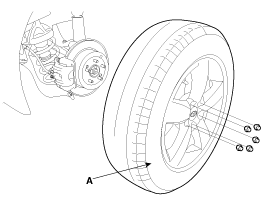
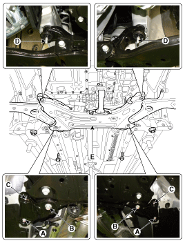
| 1. |
Remove the front wheel and tire (A) from front hub .
|

| 2. |
Disconnect the stabilizer link(B) with the front strut assembly(A)
after loosening the nut.
|
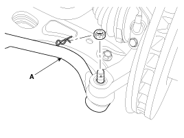
| 3. |
Remove the sprit pin and castle nut and then disconnect the tie-rod
end (A) from the front knuckle.
|
| 4. |
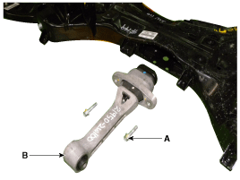
Loosen the bolt & nut and then remove the lower arm (A).
|
| 5. |
Loosen the bolt (A) and then disconnect the universal joint assembly
from the pinion of the steering gear box.
|
| 6. |
Remove the under cover.
(Refer to Engine Mechanical System - "Engine Room Under Cover")
|
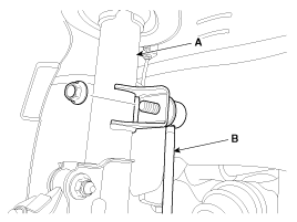
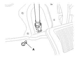
| 7. |
Loosen the bolt (A,B) and then remove the upper roll rod bracket.
|

| 8. |
Remove the roll rod stopper bolt (A).
|
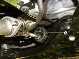
| 9. |
Disconnect the muffler rubber hanger (A).
|
| 10. |
Loosen the bolts & nuts and then remove the sub frame.
|
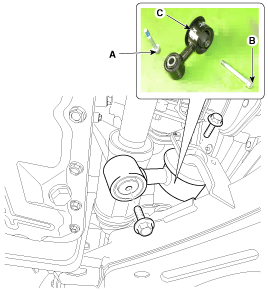
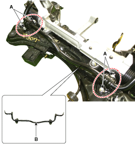
| 11. |
Loosen the bolt (A-4ea) and then remove the stabilizer bar (B)
from the sub frame.
|
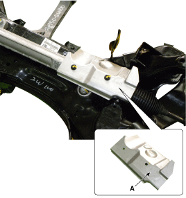
| 12. |
Loosen the bolt and then remove the protector (A).
|
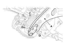
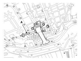
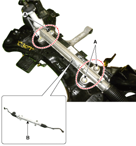
| 13. |
Remove the steering gearbox (B) from the cross member by loosening
the mounting bolt (A-4ea).
|
| 14. |
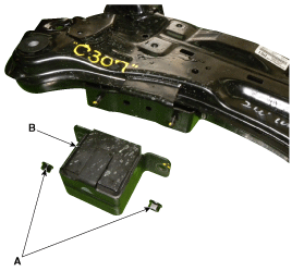
Loosen the nut (A-2ea) and then remove the sub frame damper (B).
|
| 15. |
Remove the front lower arm.
(Refer to Front Suspension System - "Front Lower Arm")
|
| 16. |
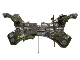
Loosen the bolt (A-2ea) and then remove the roll rod stopper (B)
from the sub frame (C).
|
| 17. |
Installation is the reverse of removal.
|
| 18. |
Check the wheel Alignment.
(Refer to Tires/Wheels - "Alignment")
|
 Front Stabilizer Bar Inspection
1.
Check the bushing for wear and deterioration.
2.
Check the front stabilizer bar for deformation.
...

See also:
Cylinder Head Cover Installation
1.
Install cylinder head cover.
(1)
The hardened liquid gasket sealant located on the upper area
between timing chain cover and cyli ...
Diagnosis With GDS
1.
BSD system defects can be quickly diagnosed with the GDS. GDS
operates actuator quickly to monitor, input/output value and self diagnosis.
2.
...
Cluster Ionizer Inspection
1.
Press the MODE switch more then 4 times within 2 seconds while
pressing the OFF switch.
Display
Fail description
00 ...
Copyright © www.ksmanual.com 2014-2024