
 Kia Sorento: Valve Body Removal
Kia Sorento (MQ4, 2021-2026) Service Manual / Automatic Transaxle System / Hydraulic System / Valve Body Removal
| Removal |
|

| 1. |
Remove the engine room under cover.
(Refer to Engine Mechanical System - "Engine Room Under
Cover")
|
| 2. |
Drain the engine coolant.
(Refer to Engine Mechanical System - "Coolant")
|
| 3. |
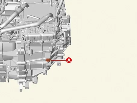
Remove the ATF drain plug (A), allow the fluid to drain out and then reinstall the drain plug.
|
| 4. |
Remove the air cleaner assembly.
(Refer to Engine Mechanical System - "Air Cleaner")
|
| 5. |
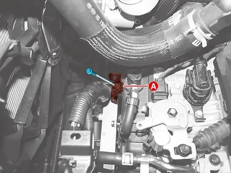
Remove the wiring bracket (A).
|
| 6. |
Remove the ATF warmer.
(Refer to Hydraulic System - "ATF Warmer")
|
| 7. |
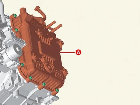
Remove the valve body cover (A) after removing the bolts.
|
| 8. |
Separate the E-module (A) after removing the bolts.
|
| 9. |
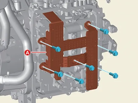
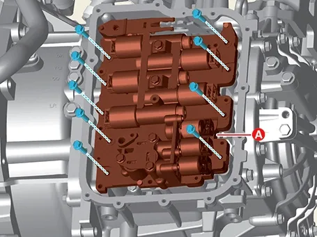
Remove the valve body assembly (A) after removing the bolts.
|
Valve Body Components and Components Location
Component
1. ATF Warmer Hose2.
Valve Body Cover2-a. 11.8 - 13.7 N·m (1.2 - 1.4 kgf·m, 8.7 ...
 Valve Body Components and Components Location. Valve Body Description and Operation
Installation
1.
Install in the reverse order of removal.
...
 Valve Body Installation
See also:
Blower Resistor Inspection
1.
Measure the resistance between the terminals.
2.
The measured resistance is not within specification, the blower
resistor must be replac ...
Auto Defogging Sensor Inspection
To inspect and diagnose the sensor, refer to Self-Diagnosis procedure
and DTC guide. ...
Front Driveshaft Components and Components Location
Components
1. Front driveshaft (LH)2. Inner shaft bearing
bracket
3. Front driveshaft (RH)
...
Manuals list
- Kia Sorento MQ4 2021-2026 Owners Manual
- Kia Sorento XM 2011-2015 Owners Manual
- Kia Sorento XM 2011-2015 Service Manual

Copyright © www.ksmanual.com 2014-2026 - 0.0495