
 Kia Sorento: Smart Key Antenna Repair Procedures
| Removal |
| 1. |
Remove the Data Connectivity Unit (DCU).
(Refer to Over The Air (OTA) - "Data Connectivity Unit
(DCU)")
|
| 2. |
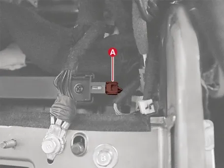
Disconnect the interior antenna 1 connector (A).
|
| 3. |
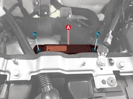
Remove the interior antenna #1 (A) after removing the screws.
|
| 1. |
Separate the front floor carpet.
(Refer to Body - "Floor Carpet")
|
| 2. |
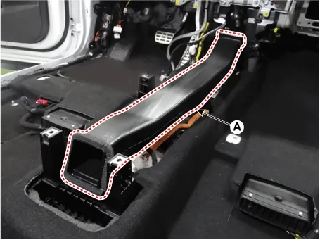
Remove the rear air duct (A).
|
| 3. |
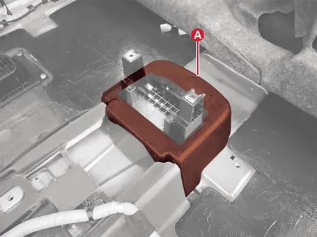
Remove the console rear bracket pad (A).
|
| 4. |
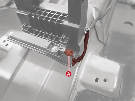
Disconnect the interior antenna 2 connector (A).
|
| 5. |
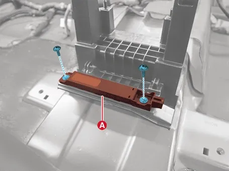
Remove the interior antenna #2 (A) after removing the screws.
|
| 1. |
Disconnect the battery negative ( - ) terminal.
|
| 2. |
Remove the rear transverse trim.
(Refer to Body - "Rear Transverse Trim")
|
| 3. |
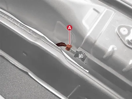
Disconnect the interior antenna 3 connector (A).
|
| 4. |
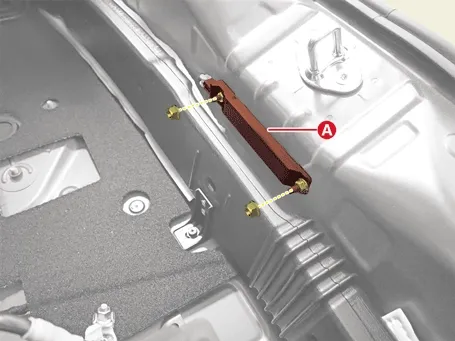
Remove the interior antenna #3 (A) after removing the nuts.
|
| 1. |
Disconnect the battery negative ( - ) terminal.
|
| 2. |
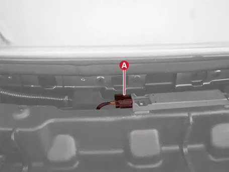
Disconnect the rear bumper beam antenna connector (A).
|
| 3. |
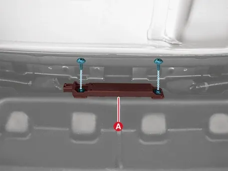
Remove the rear bumper beam antenna (A) after removing the screws.
|
| 1. |
Remove the front bumper assembly.
(Refer to Body - "Front Bumper Assembly")
|
| 2. |
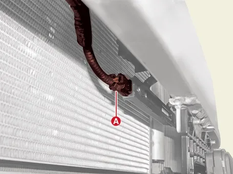
Disconnect the front bumper beam antenna connector (A).
|
| 3. |
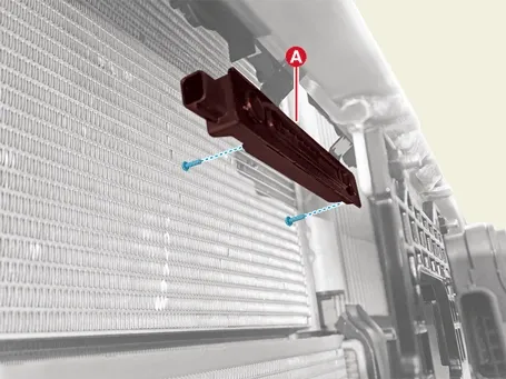
Remove the front bumper beam antenna (A) after removing the screws.
|
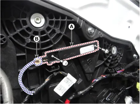
| 1. |
Remove the front door trim.
(Refer to Body - "Front Door Trim")
|
| 2. |
Remove the front door antenna (A) by removing the screws after disconnecting the connector (B).
|
| Installation |
| 1. |
Install in the reverse order of removal.
|
 On Vehicle Inspection
 Smart Key Code Saving Repair Procedures
See also:
Special Service Tools
Special Service Tool
Tool Name / Number
Illustration
Description
Engine support fixture ...
Additional safety precautions. Adding equipment to or modifying your air bag-equipped vehicle
Additional safety precautions
Never allow passengers to ride in the cargo area or on top of a folded-down back seat. All
occupants must sit upright, positioned fully back ...
Compressor Oil Specification
1.
The HFC-134a system requires synthetic (PAG) compressor oil whereas
the R-12 system requires mineral compressor oil. The two oils must never
be mixed.
...
Manuals list
- Kia Sorento MQ4 2021-2026 Owners Manual
- Kia Sorento XM 2011-2015 Owners Manual
- Kia Sorento XM 2011-2015 Service Manual
