Kia Sorento: Rear Wheel Speed Sensor Repair procedures - Electronic Stability Control (ESC) - Brake SystemKia Sorento: Rear Wheel Speed Sensor Repair procedures

Kia Sorento (MQ4, 2021-2026) Service Manual / Brake System / Electronic Stability Control (ESC) / Rear Wheel Speed Sensor Repair procedures

Removal
[2WD]
1.
Disconnect the (-) battery terminal.
2.
Remove the rear wheel and tire.
(Refer to Suspension System - "Wheel")
3.
Remove the rear wheel guard.
(Refer to Body - "Rear Wheel Guard")
4.
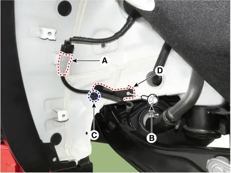
Disconnect the rear wheel speed sensor connector (A) and remove the bolt (B) and fastner (C) to remove the bracket (D).

Tightening torque :
88.3 - 107.9 N·m (2.0 - 3.0 kgf·m, 65.1 - 79.6 lb·ft)

Brake System — Electronic Stability Control (ESC) / Rear Wheel Speed Sensor / Repair procedures / Removal illustration

5.
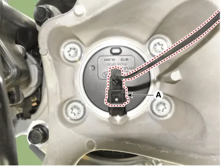
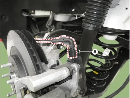
Disconnect the rear wheel sensor (A).

Brake System — Electronic Stability Control (ESC) / Rear Wheel Speed Sensor / Repair procedures / Removal illustration

6.
Remove the rear brake disc.
(Refer to Brake System - "Rear Brake Disc")
7.
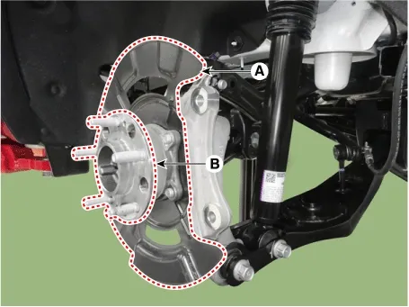
Remove the rear hub assembly mounting bolts and remove the dust cover (A) and hub (B).

Tightening torque :
88.2 - 107.8 N·m (9.0 - 11.0 kgf·m, 65.1 - 79.5 lb·ft)

Brake System — Electronic Stability Control (ESC) / Rear Wheel Speed Sensor / Repair procedures / Removal illustration

8.
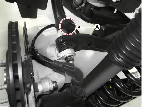
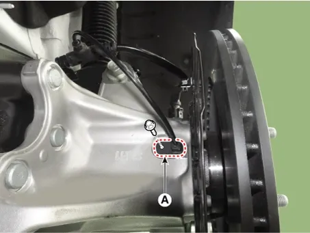
Remove the rear wheel speed sensor harness fixed fastner (A).

Brake System — Electronic Stability Control (ESC) / Rear Wheel Speed Sensor / Repair procedures / Removal illustration

9.
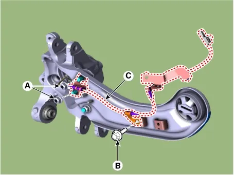
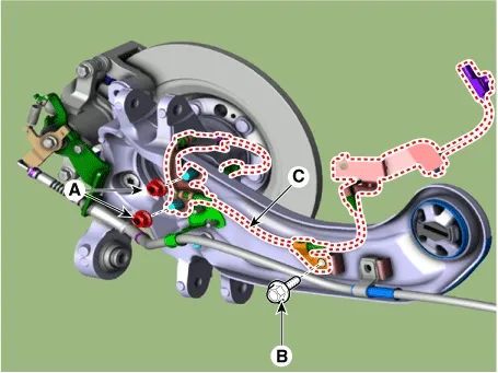
Remove the bracket mounting nuts (A) and bolt (B) and remove the rear wheel speed sensor harness (C).
[EPB Apply]

Tightening torque
Nuts (A) : 6.9 - 10.8 N·m (0.7 - 1.1 kgf·m, 5.1 - 7.9 lb·ft)
Bolt (B) : 12.7 - 16.7 N·m (1.3 - 1.7 kgf·m, 9.4 - 12.3 lb·ft)

Brake System — Electronic Stability Control (ESC) / Rear Wheel Speed Sensor / Repair procedures / Removal illustration

[EPB None Apply]

Tightening torque
Nuts (A) : 98.1 - 117.6 N·m (10.0 - 12.0 kgf·m, 72.3 - 86.8 lb·ft)
Bolt (B) : 12.7 - 16.7 N·m (1.3 - 1.7 kgf·m, 9.4 - 12.3 lb·ft)

Brake System — Electronic Stability Control (ESC) / Rear Wheel Speed Sensor / Repair procedures / Removal illustration

[AWD]
1.
Disconnect the (-) battery terminal.
2.
Remove the rear wheel and tire.
(Refer to Suspension System - "Wheel")
3.
Remove the rear wheel guard.
(Refer to Body - "Rear Wheel Guard")
4.
Disconnect the rear wheel speed sensor connector (A) and remove the bolt (B) and fastner (C) to remove the bracket (D).

Tightening torque :
88.3 - 107.9 N·m (2.0 - 3.0 kgf·m, 65.1 - 79.6 lb·ft)

Brake System — Electronic Stability Control (ESC) / Rear Wheel Speed Sensor / Repair procedures / Removal illustration

5.
Disconnect the rear wheel sensor (A).

Tightening torque :
8.8 - 13.7 N·m (0.9 - 1.4 kgf·m, 6.5 - 10.1 lb·ft)

Brake System — Electronic Stability Control (ESC) / Rear Wheel Speed Sensor / Repair procedures / Removal illustration

6.
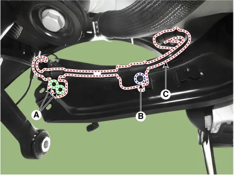
Remove the rear wheel speed sensor harness fixed fastner (A).

Brake System — Electronic Stability Control (ESC) / Rear Wheel Speed Sensor / Repair procedures / Removal illustration

7.
Disconnect the EPB actuator connector (A). [EPB Apply]

Brake System — Electronic Stability Control (ESC) / Rear Wheel Speed Sensor / Repair procedures / Removal illustration

8.
Remove the bracket mounting nuts (A) and bolt (B) and remove the rear wheel speed sensor harness (C).
[EPB Apply]

Tightening torque
Nuts (A) : 6.9 - 10.8 N·m (0.7 - 1.1 kgf·m, 5.1 - 7.9 lb·ft)
Bolt (B) : 12.7 - 16.7 N·m (1.3 - 1.7 kgf·m, 9.4 - 12.3 lb·ft)

Brake System — Electronic Stability Control (ESC) / Rear Wheel Speed Sensor / Repair procedures / Removal illustration

[EPB None Apply]

Tightening torque
Nuts (A) : 98.1 - 117.6 N·m (10.0 - 12.0 kgf·m, 72.3 - 86.8 lb·ft)
Bolt (B) : 12.7 - 16.7 N·m (1.3 - 1.7 kgf·m, 9.4 - 12.3 lb·ft)

Brake System — Electronic Stability Control (ESC) / Rear Wheel Speed Sensor / Repair procedures / Removal illustration

Replacement
Rear Wheel Speed Sensor Cap [2WD Only]
1.
Remove the rear wheel hub bearing assembly.
(Refer to Driveshaft and axle - "Rear Axle Assembly")
2.
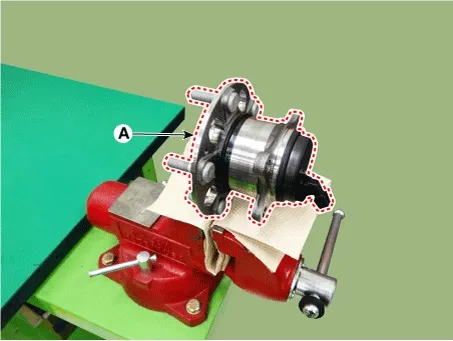
Fix the rear hub bearing assembly (A) on the vise.

Brake System — Electronic Stability Control (ESC) / Rear Wheel Speed Sensor / Repair procedures / Replacement illustration

Note
•
When placing on the vise, use a cloth not to be damaged the hub bearing assembly.
•
Be careful not to use excessive force on the vise may damage the hub bearing assembly.
3.
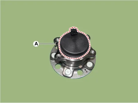
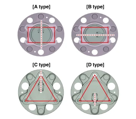
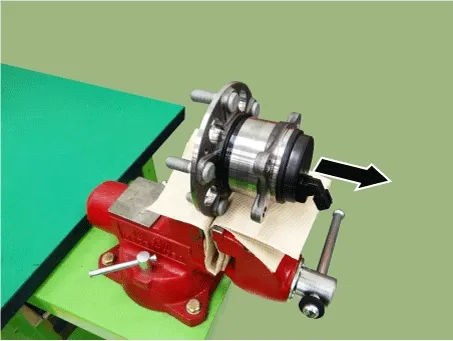
Check the direction of the sensor cap (A).

Brake System — Electronic Stability Control (ESC) / Rear Wheel Speed Sensor / Repair procedures / Replacement illustration

Note
Before removing the sensor cap, check the direction of the sensor cap connector.

Brake System — Electronic Stability Control (ESC) / Rear Wheel Speed Sensor / Repair procedures / Replacement illustration

4.
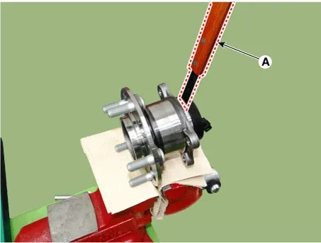
Remove the sensor cap by hammering on a gap between sensor cap and hub bearing assembly using a scraper (A).

Brake System — Electronic Stability Control (ESC) / Rear Wheel Speed Sensor / Repair procedures / Replacement illustration

Note
•
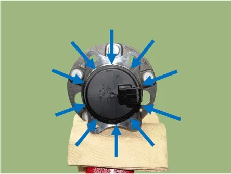
In order to widen the gap little by little, hammering around the bearing cap 10-20 times.

Brake System — Electronic Stability Control (ESC) / Rear Wheel Speed Sensor / Repair procedures / Replacement illustration

•
When removing the sensor cap, remove it in a straight direction not to damage the tone wheel or encoder.

Brake System — Electronic Stability Control (ESC) / Rear Wheel Speed Sensor / Repair procedures / Replacement illustration

•
Be careful not to damage the hub bearing assembly when using the hammer.
5.
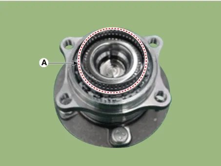
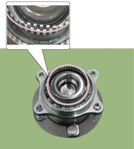
Check for distortion of damage of the tone wheel or encoder (A).

Brake System — Electronic Stability Control (ESC) / Rear Wheel Speed Sensor / Repair procedures / Replacement illustration

Note
•
Check if damaged the tone wheel or encoder after removing the sensor cap and replace the hub bearing if it was deformed.
•
If the tone wheel is deformed, it may trigger the MIL ON or other problems.

Brake System — Electronic Stability Control (ESC) / Rear Wheel Speed Sensor / Repair procedures / Replacement illustration

6.
Position the sensor cap to the same direction of sensor cap connector (A) as you checked before removing.

Brake System — Electronic Stability Control (ESC) / Rear Wheel Speed Sensor / Repair procedures / Replacement illustration

Note
Before installing the sensor cap, do not let any foreign material and contaminant into the hub bearing assembly.
7.
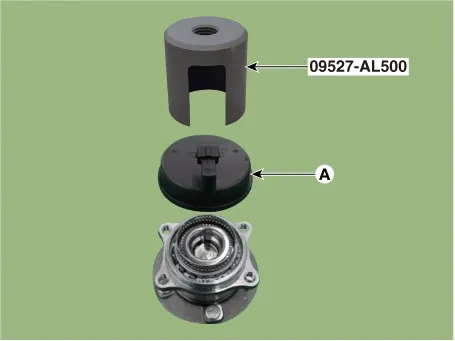
Install the sensor cap (A) with the special service tool (09527-AL500).

Brake System — Electronic Stability Control (ESC) / Rear Wheel Speed Sensor / Repair procedures / Replacement illustration

Note
•
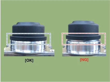
Be careful not to tilt to one side when installing the sensor cap as it may damage the tone wheel or encoder.
•
When sensor cap installation, hammering it until the gap disappeared between the sensor cap and hub bearing assembly.

Brake System — Electronic Stability Control (ESC) / Rear Wheel Speed Sensor / Repair procedures / Replacement illustration

•
Special Service Tools guide.
SST No.
SST Inner diameter
Sensor cap outer diameter
09527-2W110
Φ82.1
Φ81.2, Φ81.4
09527-1S010
Φ58.9
Φ58.4
09527-AL100
Φ60
Φ59.5
09527-AL200
Φ65.9
Φ65.3
09527-AL300
Φ67.4
Φ67.2
09527-AL400
Φ73.2
Φ72.6
09527-AL500
Φ87.2
Φ86.6

8.
Install the rear wheel hub bearing assembly.
(Refer to Driveshaft and axle - "Rear Axle Assembly")
Inspection
1.
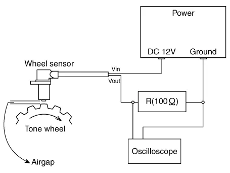
Measure the output voltage between the terminal of the wheel speed sensor and the body ground.
Note
In order to protect the wheel speed sensor, when measuring output voltage, a 100Ω resister must be used as shown.

Brake System — Electronic Stability Control (ESC) / Rear Wheel Speed Sensor / Repair procedures / Inspection illustration

2.
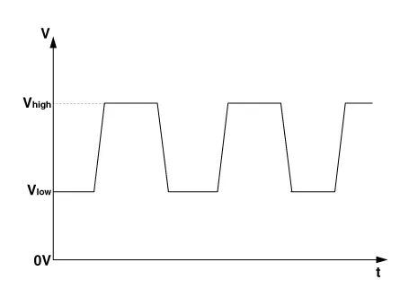
Compare the change of the output voltage of the wheel speed sensor to the normal change of the output voltage as shown below.

Brake System — Electronic Stability Control (ESC) / Rear Wheel Speed Sensor / Repair procedures / Inspection illustration

- Ilow : 7 ± 1.05 mA
- Ihigh : 14 ± 2.1 mA
- Frequency range : 0.03 - 3,000 Hz
Installation
1.
Install in the reverse order of removal.
Rear Wheel Speed Sensor Components and Components Location

Components [2WD] [EPB Apply] 1. Rear wheel speed sensor 2. Rear wheel speed sensor connector [E...
Body (Interior and Exterior)
...
See also:

Special Service Tools
Special Service Tools Tool Name / Number Illustration Description Fuel pressure gauge09353 - 24100 ...

Torque Converter Control Solenoid Valve (T/CON_VFS)
Torque converter control solenoid valve (T/CON) is attached to the valve body. This variable force solenoid valve directly controls the hydraulic pressure inside the torque converter. ...

Power Tailgate Unit Removal
1. Disconnect the negative (-) battery terminal. 2. Remove the rear left luggage side trim. (Refer to Body - "Interior Trim") ...

Copyright © www.ksmanual.com 2014-2026 - 0.0659