Kia Sorento: Rear Hub - Carrier Repair procedures - Rear Axle Assembly - Driveshaft and axleKia Sorento: Rear Hub - Carrier Repair procedures

Kia Sorento (MQ4, 2021-2026) Service Manual / Driveshaft and axle / Rear Axle Assembly / Rear Hub - Carrier Repair procedures

Removal
[2WD]
1.
Disconnect the (-) battery terminal.
2.
Remove the rear wheel and tire.
(Refer to Suspension System - "Wheel")
3.
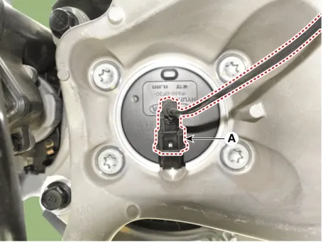
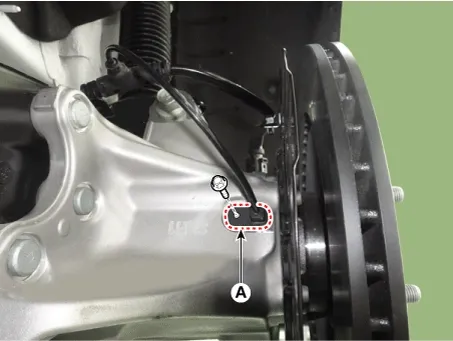
Disconnect the rear wheel speed sensor connector (A).

Driveshaft and axle — Rear Axle Assembly / Rear Hub - Carrier / Repair procedures / Removal illustration

4.
Remove the rear brake disc.
(Refer to Brake System - "Rear Brake Disc")
5.
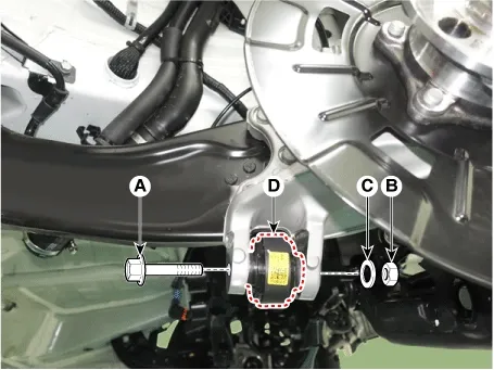
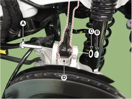
Remove the bolt (A), nut (B) and washer (C) to separate the rear assist arm (D) from the rear carrier.

Tightening torque :
156.9 - 176.5 N·m (16.0 - 18.0 kgf·m, 115.7 - 130.1 lb·ft)

Driveshaft and axle — Rear Axle Assembly / Rear Hub - Carrier / Repair procedures / Removal illustration

Note
•
When removing the bolt, install the transmission jack and remove it under no load.
•
Mark the bolt, nut and washer in advance so that they do not change position and orientation.
6.
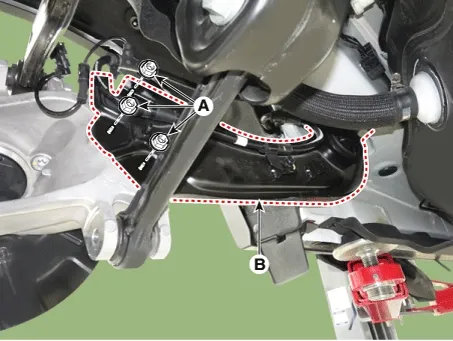
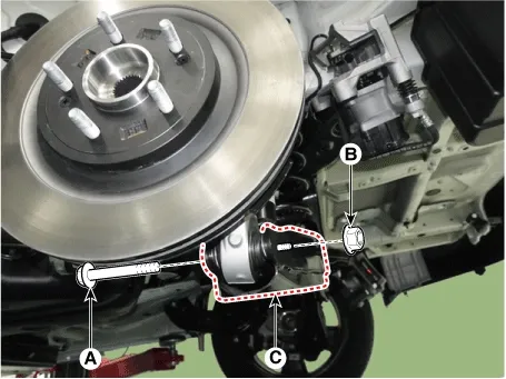
Remove the nut (A) and remove the trailing arm (B) from the rear carrier.

Tightening torque :
98.1 - 117.7 N·m (10.0 - 12.0 kgf·m, 72.3 - 86.8 lb·ft)

Driveshaft and axle — Rear Axle Assembly / Rear Hub - Carrier / Repair procedures / Removal illustration

Note
•
When removing the bolt, install the transmission jack and remove it under no load.
•
Mark the bolt, nut and washer in advance so that they do not change position and orientation.
7.
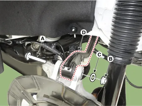
Remove the bolt (A), nut (B) and washer (C) to separate the rear upper arm (D) from the rear carrier.

Tightening torque :
156.9 - 176.5 N·m (16.0 - 18.0 kgf·m, 115.7 - 130.1 lb·ft)

Driveshaft and axle — Rear Axle Assembly / Rear Hub - Carrier / Repair procedures / Removal illustration

Note
•
When removing the bolt, install the transmission jack and remove it under no load.
•
Mark the bolt, nut and washer in advance so that they do not change position and orientation.
8.
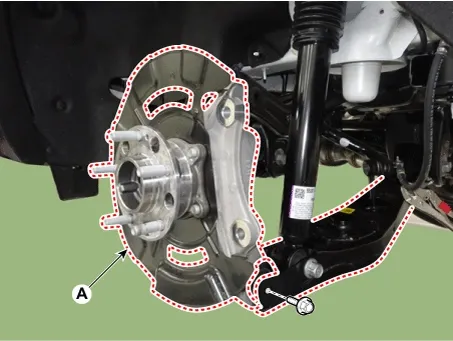
Remove the rear lower arm fixing bolts and nuts and remove the rear hub carrier (A).

Tightening torque :
156.9 - 176.5 N·m (16.0 - 18.0 kgf·m, 115.7 - 130.1 lb·ft)

Driveshaft and axle — Rear Axle Assembly / Rear Hub - Carrier / Repair procedures / Removal illustration

[AWD]
1.
Disconnect the (-) battery terminal.
2.
Remove the rear wheel and tire.
(Refer to Suspension System - "Wheel")
3.
Disconnect the rear wheel speed sensor connector (A).

Tightening torque :
8.8 - 13.7 N·m (0.9 - 1.4 kgf·m, 6.5 - 10.1 lb·ft)

Driveshaft and axle — Rear Axle Assembly / Rear Hub - Carrier / Repair procedures / Removal illustration

4.
Remove the rear brake caliper.
(Refer to Brake System - "Rear Brake Caliper")
5.
Remove the bolt (A), nut (B) and washer (C) to separate the rear assist arm (D) from the rear carrier.

Tightening torque :
156.9 - 176.5 N·m (16.0 - 18.0 kgf·m, 115.7 - 130.1 lb·ft)

Driveshaft and axle — Rear Axle Assembly / Rear Hub - Carrier / Repair procedures / Removal illustration

Note
•
When removing the bolt, install the transmission jack and remove it under no load.
•
Mark the bolt, nut and washer in advance so that they do not change position and orientation.
6.
Remove the nut (A) and remove the trailing arm (B) from the rear carrier.

Tightening torque :
98.1 - 117.7 N·m (10.0 - 12.0 kgf·m, 72.3 - 86.8 lb·ft)

Driveshaft and axle — Rear Axle Assembly / Rear Hub - Carrier / Repair procedures / Removal illustration

Note
•
When removing the bolt, install the transmission jack and remove it under no load.
•
Mark the bolt, nut and washer in advance so that they do not change position and orientation.
7.
Remove the bolt (A), nut (B) and washer (C) to separate the rear upper arm (D) from the rear carrier.

Tightening torque :
156.9 - 176.5 N·m (16.0 - 18.0 kgf·m, 115.7 - 130.1 lb·ft)

Driveshaft and axle — Rear Axle Assembly / Rear Hub - Carrier / Repair procedures / Removal illustration

Note
•
When removing the bolt, install the transmission jack and remove it under no load.
•
Mark the bolt, nut and washer in advance so that they do not change position and orientation.
8.
Remove the rear lower arm fixing bolts and nuts and remove the rear hub carrier (A).

Tightening torque :
156.9 - 176.5 N·m (16.0 - 18.0 kgf·m, 115.7 - 130.1 lb·ft)

Driveshaft and axle — Rear Axle Assembly / Rear Hub - Carrier / Repair procedures / Removal illustration


Note
•
When removing the bolt, install the transmission jack and remove it under no load.
•
Mark the bolt, nut and washer in advance so that they do not change position and orientation.
9.
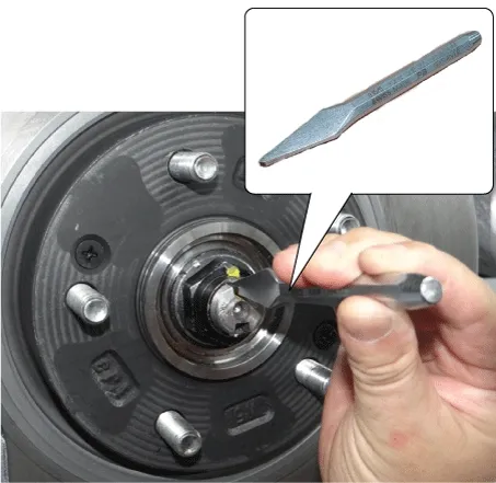
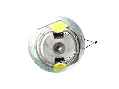
By hammering on a chisel, unlock the driveshaft lock hub nut caulking.

Driveshaft and axle — Rear Axle Assembly / Rear Hub - Carrier / Repair procedures / Removal illustration

Note
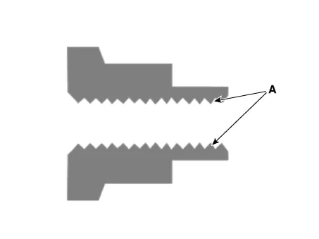
If there is screw thread (A) on the end of the nut, unlock the caulking by using a chisel and then remove the nut to prevent damaging driveshaft screw thread.

Driveshaft and axle — Rear Axle Assembly / Rear Hub - Carrier / Repair procedures / Removal illustration

10.
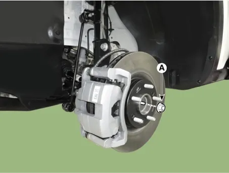
Remove the caulking nut (A) from the front axle.

Tightening torque :
294.2 - 313.8 N·m (30.0 - 32.0 kgf·m, 217.0 - 231.5 lb·ft)

Driveshaft and axle — Rear Axle Assembly / Rear Hub - Carrier / Repair procedures / Removal illustration

Note
•
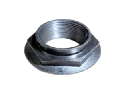
The driveshaft lock nut must be replaced with new one. When replacing the drive lock hub nut, use only the nut with screw thread (A) on the end.

Driveshaft and axle — Rear Axle Assembly / Rear Hub - Carrier / Repair procedures / Removal illustration

•
When replacing the drive lock hub nut, use only the nut with screw thread (A) on the end.

Driveshaft and axle — Rear Axle Assembly / Rear Hub - Carrier / Repair procedures / Removal illustration

•
Tighten the driveshaft lock hub nut to the specified tightening torque, and caulk by using a chisel and hammer.
•
If there are two key seats, perform on all two seats.

Caulking depth (A) : 1.5 mm (0.0591 in)

Driveshaft and axle — Rear Axle Assembly / Rear Hub - Carrier / Repair procedures / Removal illustration

11.
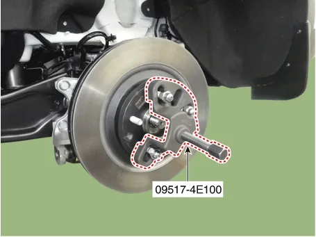
Disconnect the driveshaft from the axle hub by using the SST (09517-4E000).

Driveshaft and axle — Rear Axle Assembly / Rear Hub - Carrier / Repair procedures / Removal illustration

Note
Removing the driveshaft, do not force pull or over deflect the axle.
12.
Remove the rear carrier assembly (A).

Driveshaft and axle — Rear Axle Assembly / Rear Hub - Carrier / Repair procedures / Removal illustration

Disassembly
[2WD]
1.
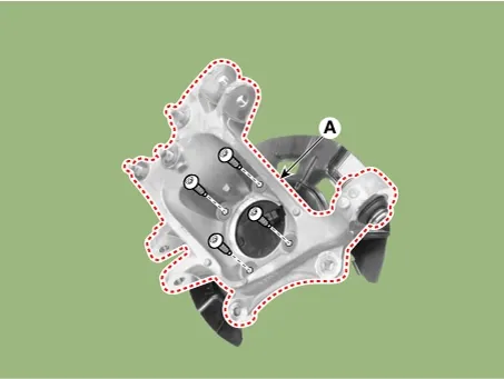
Remove the hub bearing mounting bolts from the rear knuckle (A).

Tightening torque :
88.2 - 107.8 N·m (9.0 - 11.0 kgf·m, 65.1 - 79.5 lb·ft)

Driveshaft and axle — Rear Axle Assembly / Rear Hub - Carrier / Repair procedures / Disassembly illustration

[AWD]
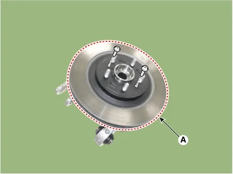
1.
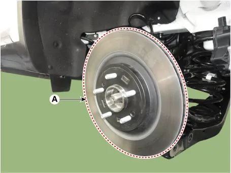
Remove the screws and then remove the rear brake disc (A).

Tightening torque :
4.9 - 5.9 N·m (0.5 - 0.6 kgf·m, 3.6 - 4.3 lb·ft, 43.4 - 52.1 lb-in)

Driveshaft and axle — Rear Axle Assembly / Rear Hub - Carrier / Repair procedures / Disassembly illustration

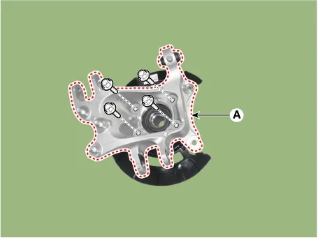
2.
Remove the hub bearing mounting bolts from the rear knuckle (A).

Tightening torque :
88.2 - 107.8 N·m (9.0 - 11.0 kgf·m, 65.1 - 79.5 lb·ft)

Driveshaft and axle — Rear Axle Assembly / Rear Hub - Carrier / Repair procedures / Disassembly illustration

Inspection
1.
Check the hub for cracks and the splines for wear.
2.
Check the brake disc for scoring and damage.
3.
Check the rear axle carrier for cracks.
4.
Check the bearing for cracks or damage.
Reassembly
1.
Assemble in the reverse order of disassembly.
Installation
1.
Install in the reverse order of removal.
2.
Check the rear alignment.
(Refer to Suspension System - "Alignment")
Rear Hub - Carrier Components and Components Location
Components 1. Rear brake disc2. Rear hub assembly 3. Dust cover4. Rear carrier...

Driveshaft Assembly
...
See also:

Disassembly
1. Remove the steering wheel cover (B) after loosening the screw (A-6ea). 2. Disconnect the streeing wheel remote control s ...

Ambient Temperature Sensor Inspection
Inspection 1. Change the temperature around the ambient temperature sensor and check if the resistance value of 1 - 2 termi ...

Oil hydraulic Motor(Actuator) Circuit Diagram
...

Copyright © www.ksmanual.com 2014-2026 - 0.0602