
 Kia Sorento: Rear Differential Carrier Repair procedures
| Removal |
| 1. |
Disconnect the (-) battery terminal.
|
| 2. |
Remove the rear driveshaft.
(Refer to Rear Driveshaft Assembly - "Rear Driveshaft")
|
| 3. |
Remove the propeller shaft.
(Refer to Propeller Shaft Assembly - "Propeller Shaft")
|
| 4. |
Remove the coupling assembly.
(Refer to All Wheel Drive (AWD) System - "Direct Electro Hydraulic
Actuator Coupling")
|
| 5. |
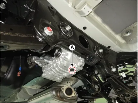
Remove the drain plug (A) to drain the gear oil before removing the rear differential carrier.
|

| 6. |
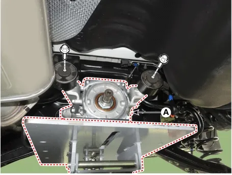
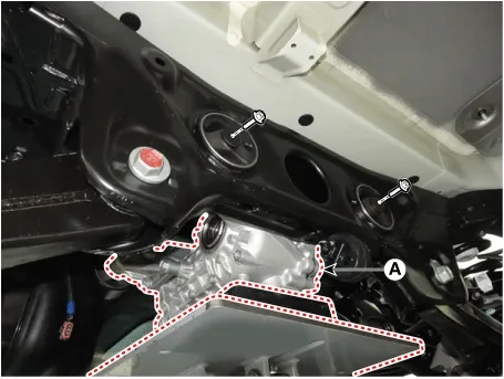
Install the jack and remove the differential mounting bolts to remove the rear differential assembly (A).
[Front]
[Rear]
|
| 7. |
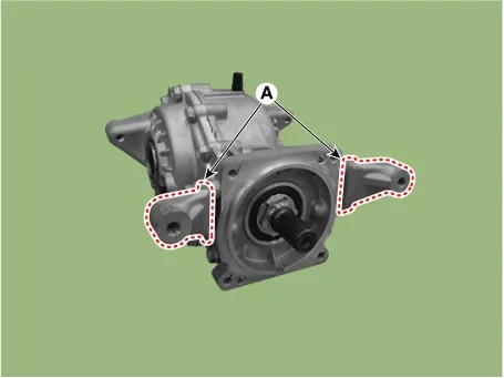
Remove the bolts and remove the differential carrier bracket (A).
|
| Disassembly |
| 1. |
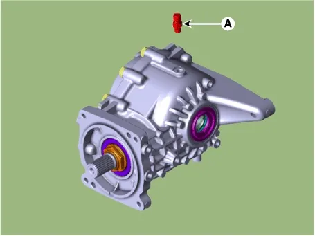
Remove the air breather (A).
|
| 2. |
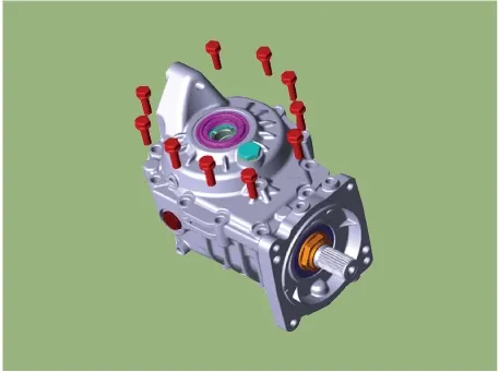
Remove the differential carrier side cover fixing bolts.
|
| 3. |
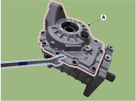
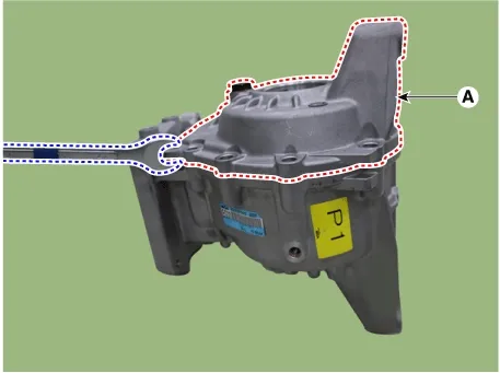
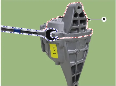
Widen the gap between the side cover and the case to remove the side cover (A).
|
| 4. |
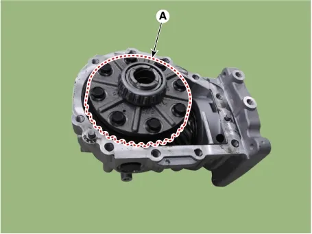
Remove the differential gear assembly (A).
|
| 5. |
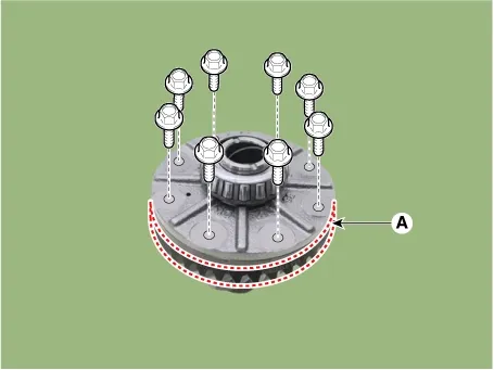
Remove the bolt and remove the ring gear (A) from the gear carrier.
|
| 6. |
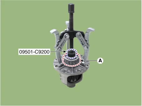
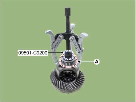
Remove the differential gear bearing (A) using SST (09501-C9200) and puller.
[Differential carrier cover side]
[Differential carrier side]
|
| 1. |
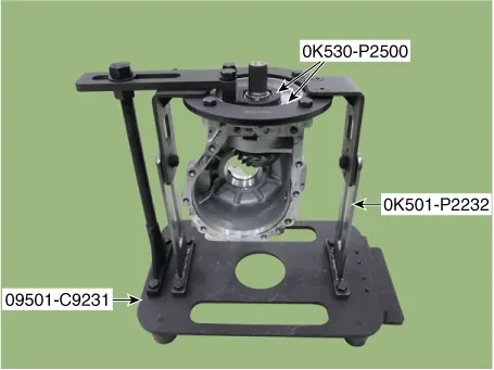
Fix the differential carrier assembly using SST (09501-C9230, 0K530-P2500, 0K501-P2232).
|
| 2. |
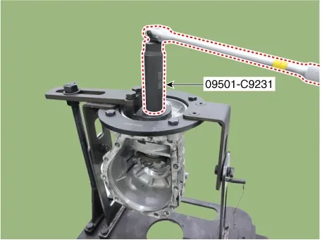
Remove the pinion gear lock nut using SST (09501-C9230).
|
| 3. |
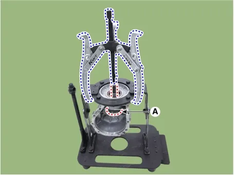
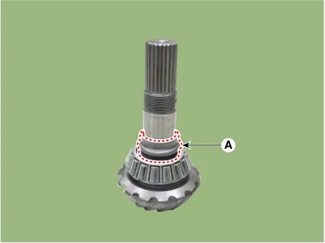
Remove the pinion drive gear assembly (A) using puller.
|
| 4. |
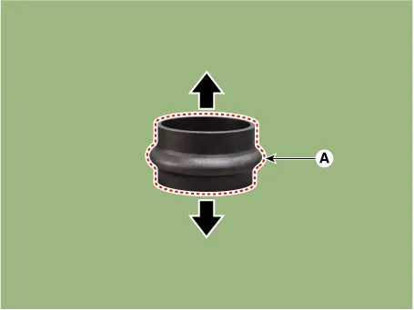
Remove the spacer (A) from pinion drive gear assembly.
|

| 5. |
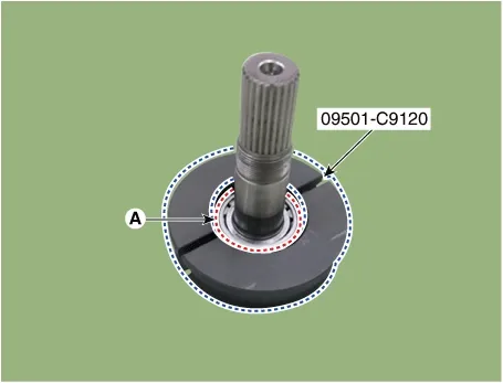
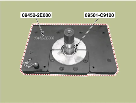
Install SST (09501-C9120, 09452-2E000) and remove the bearing (A) from the pinion drive gear using a press.
|
| 6. |
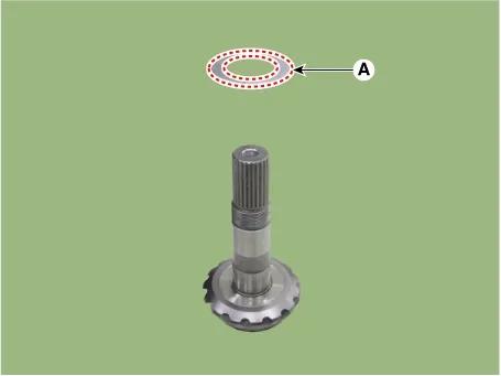
Remove the pinion inner bearing adjustment shim (A) from the pinion drive gear.
|
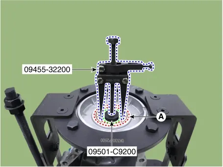
| 1. |
Remove the pinion oil seal (A) using SST (09455-32200, 09501-C9200).
|
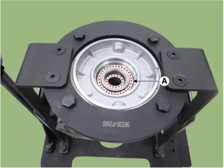
| 2. |
Remove the outer pinion bearing (A).
|
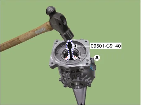
| 3. |
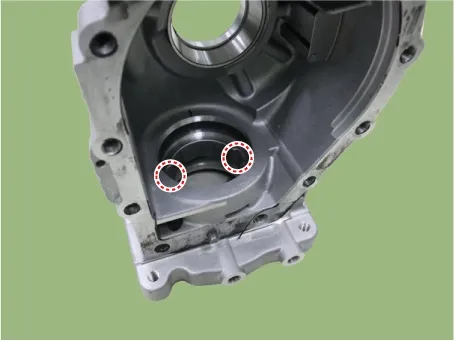
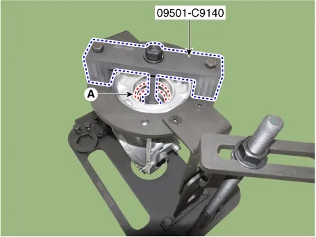
Remove the inner pinion bearing race (A) using SST (09501-C9140).
|

| 4. |
Remove the outer pinion bearing race (A) using SST (09501-C9140).
|
| 5. |
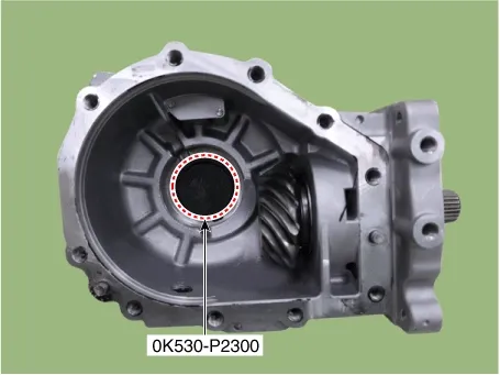
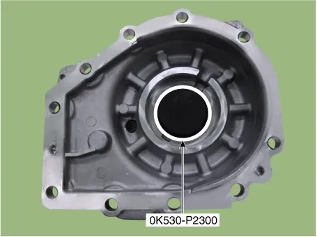
Remove the differential carrier case side oil seal (A) using SST (0K530-P2300).
|
| 6. |
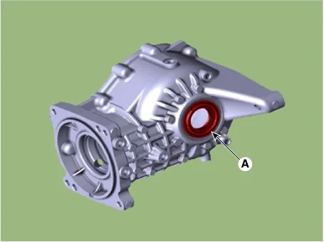
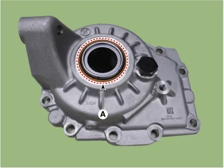
Remove the differential carrier case side cover oil seal (A) using SST (0K530-P2300).
|
| 7. |
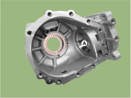
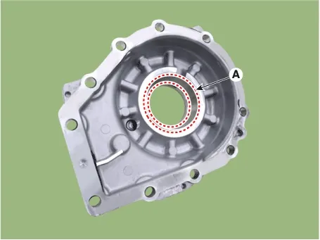
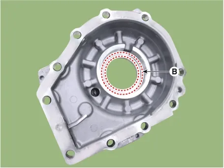
Remove the differential carrier case side bearing race (A) and adjustment shim (B).
|
| 8. |
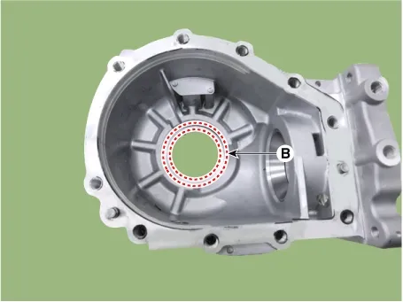
Remove the differential carrier case side cover bearing race (A) and adjustment shim (B).
|
| 9. |
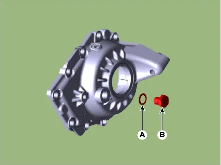
Remove the filler gasket (A) and filler plug (B) from the differential carrier case side cover.
|
| Inspection |
| 1. |
After clearing, check for damaged or worn parts and follow the methods below if applicable.
|
| 2. |
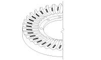
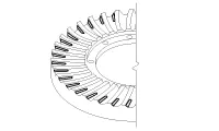
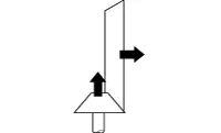
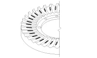
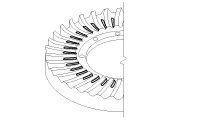
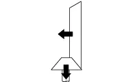
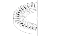
Check the tooth contact pattern.
|
||||||||||||||||||||||||||||
| Reassembly |
| 1. |
Install the inner pinion bearing adjustment shim (A) on the pinion drive gear assembly.
|
| 2. |
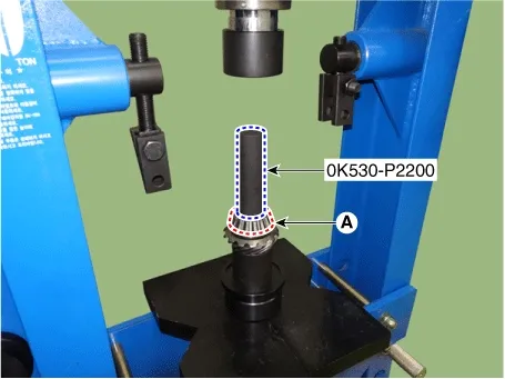
Install the inner pinion bearing (A) on the pinion drive gear using SST (0K530-P2300) and press.
|
| 3. |
Install the spacer (A) in the pinion drive gear assembly.
|
| 1. |
Install the ring gear (A) on the gear carrier.
|
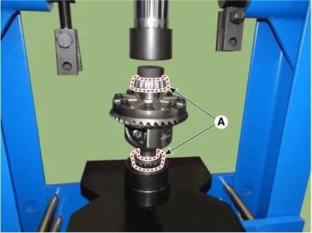
| 2. |
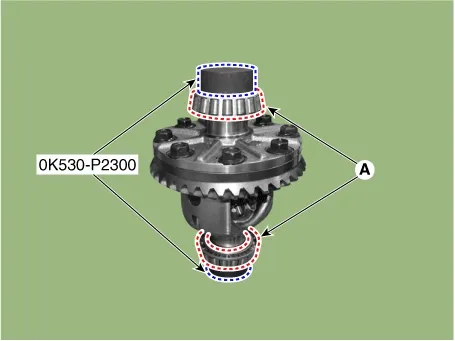
Install the differential gear bearings (A) on both sides using SST (0K530-P2300) and press.
|
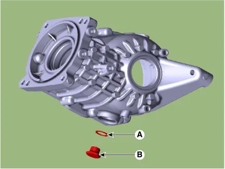
| 1. |
Install the drain plug packing (A) and drain plug (B) in the differential carrier.
|
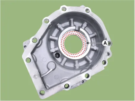
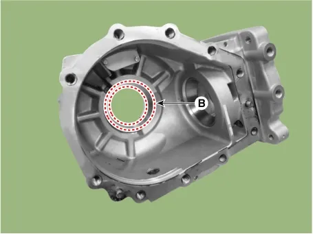
| 2. |
Install the differential carrier case side cover bearing adjustment shim (A) and race (B).
|
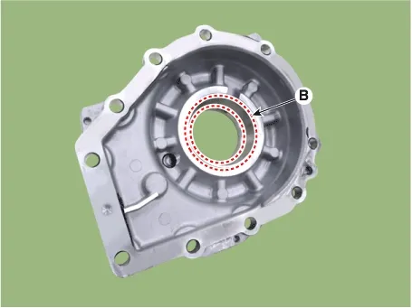
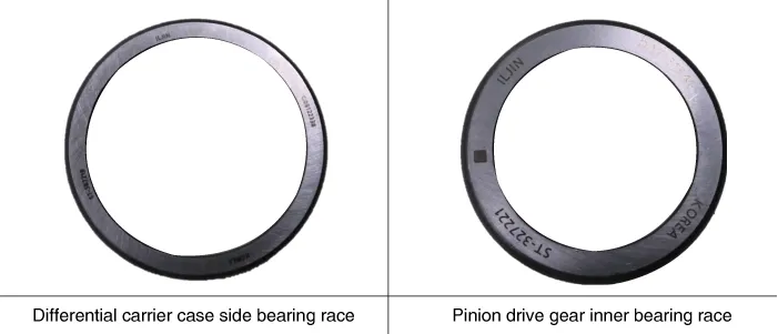
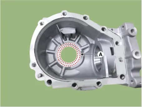
| 3. |
Install the differential carrier case side bearing adjustment shim (A) and race (B).
|
| 4. |
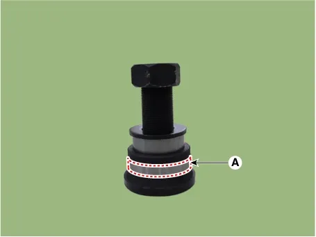
Install the outer pinion bearing race using SST (09501-C9150).
|
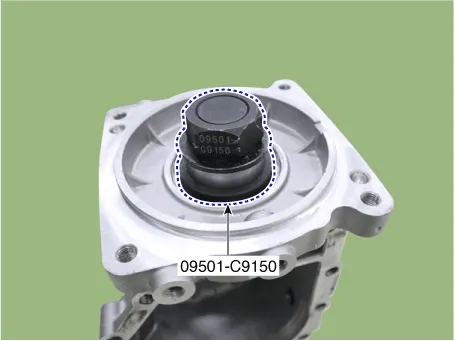
| 5. |
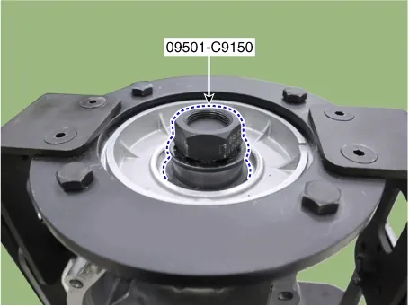
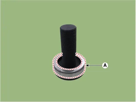
Install the inner pinion bearing race (A) using SST (09501-C9150).
|
| 6. |
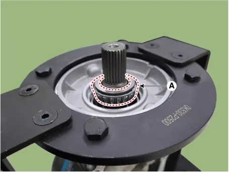
Install outer pinion bearing (A) on pinion gear assembly.
|
| 7. |
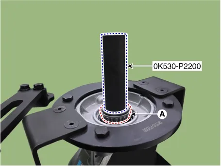
Place the SST (0K530-P2200) on the pinion gear spline side and hammer the top of the SST (0K530-P2200)
until the thread can engages the lock nut.
|
| 8. |
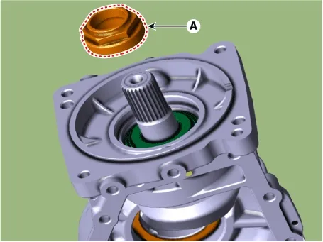
Pre-tighten the pinion lock nut (A) to the thread on the side of the pinion gear spline.
|
| 9. |
Hold the differential carrier assembly using SST (09501-C9231, 0K530-P2500, 0K501-P2232).
|
| 10. |
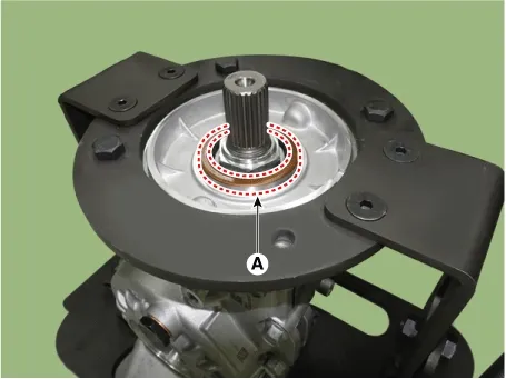
Tighten the pinion gear lock nut (A) using SST (09501-C9231) to press the outer bearing.
|
| 11. |
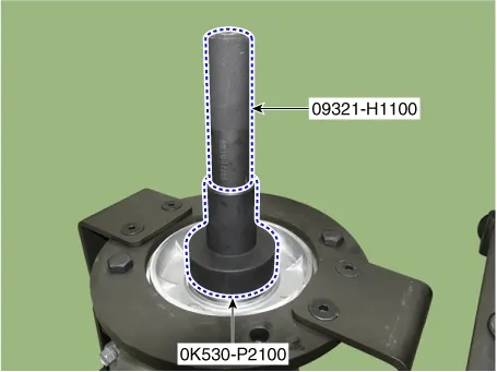
Press the pinion oil seal (A) using SST (0K530-P2100, 09231-H1100).
|
| 12. |
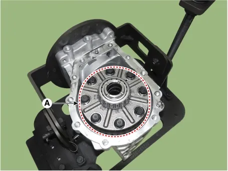
Install the differential gear assembly (A) in the differential carrier case.
|
| 13. |
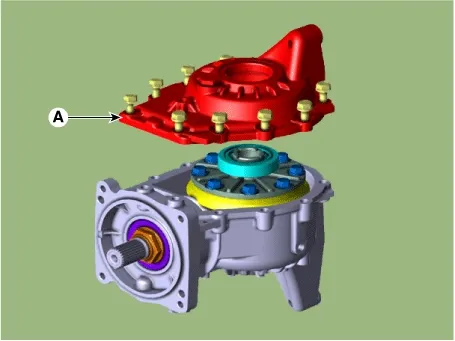
Install the differential carrier case side cover (A).
|
| 14. |
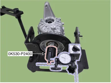
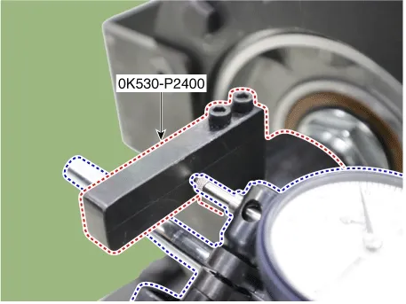
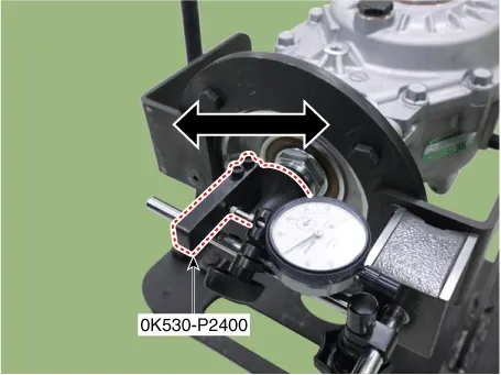
Install SST (0K530-P2400) on the pinion drive gear spline side and set the dial gauge on the case.
|
| 15. |
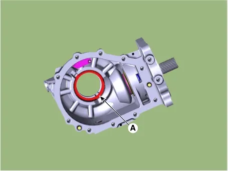
After moving the SST (0K530-P2400) left and right, read the dial gauge and measure the backlash.
|
| 16. |
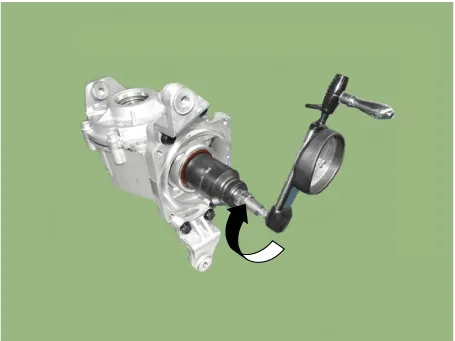
Measure the total preload.
|
| 17. |
Remove the bolt and remove the differential carrier case side cover (A).
|
| 18. |
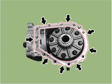
Apply the sealant on the adhesive side between differential carrier case and side cover.
|
| 19. |
Install the differential case side cover (A).
|
| 20. |
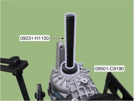
Install the oil seal on both sides of the differential carrier case using SST (09501-C9190, 09231-H1100).
|
| 21. |
Install the air breather (A).
|
| Installation |
| 1. |
Install the differential carrier bracket (A).
|
| 2. |
Install the jack and intall the differential carrier assembly (A).
[Front]
[Rear]
|
| 3. |
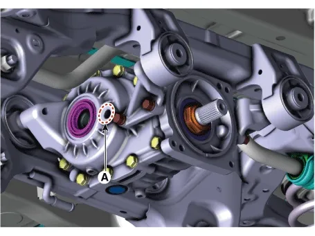
Add new gear oil through filler plug hole (A).
|
| 4. |
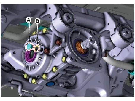
Install the filler plug (A) and filler gasket (B).
|
| 5. |
Install the coupling assembly.
(Refer to All Wheel Drive (AWD) System - "Direct Electro Hydraulic
Actuator Coupling")
|
| 6. |
Install the propeller shaft.
(Refer to Propeller Shaft Assembly - "Propeller Shaft")
|
| 7. |
Install the rear driveshaft.
(Refer to Rear Driveshaft Assembly - "Rear Drive Shaft")
|
| 8. |
Install the rear wheel and tire.
(Refer to Suspension System - "Wheel")
|
| 9. |
Connect the ( - ) battery terminal.
|
| 10. |
Check the rear alignment.
(Refer to Suspension System - "Alignment")
|
 Rear Differential Carrier Components and Components Location
 Suspension System
See also:
CVVT (Continuously Variable Valve Timing) System Operation Principle
The CVVT has the mechanism rotating the rotor vane with hydraulic force
generated by the engine oil supplied to the advance or retard chamber in accordance
with the CVVT oil control valve con ...
Components and Components Location
Components (1)
1. Parking brake pedal
2. Equalizer assembly
3. Parking brake cable
Components (2)
1. Parking brake pedal assembly
2. Front parking brak ...
Rear PWM-FET Inspection
Inspection
1.
IG ON.
2.
Measure the voltage of the 2 - 4 terminals of the blow ...
Manuals list
- Kia Sorento MQ4 2021-2026 Owners Manual
- Kia Sorento XM 2011-2015 Owners Manual
- Kia Sorento XM 2011-2015 Service Manual
