 Kia Sorento: On Vehicle Inspection
Inspection Item
|
•
|
Battery efficiency inspection
|
|
•
|
Battery voltage inspection
|
|
•
|
Charging voltage inspection
|
|
•
|
Terminal tightening state inspection
|
|
•
|
Engine/ transaxle ground state inspection
|
|
•
|
Wiring harness ground state inspection
|
|
•
|
Electrical Specified Value Inspection
|
|
•
|
Vehicle parasitic current inspection
|
|
•
|
Inspect the battery capacity
|
Battery Efficiency Inspection
|
•
|
Check that the battery cables are connected to the correct terminals.
|
|
•
|
Disconnect the battery cables when the battery is given a quick charge.
|
|
•
|
Never disconnect the battery while the engine is running.
|
|
|
Inspect the battery test using the load tester and battery tester.
|
Battery Voltage Inspection
| 1. |
After having driven the vehicle and in the case that 20 minutes have not passed after having stopped the
engine, turn the ignition switch ON and turn on the electrical system (headlamp, blower motor, rear defogger
etc.) for 60 seconds to remove the surface charge.
|
| 2. |
Turn the ignition switch OFF and turn off the electrical systems.
|
| 3. |
Measure the battery voltage between the negative (-) and positive (+) terminals of the battery.
Standard voltage (V) : About 12.5 - 12.9 [20°C (60°F)]
|
If the voltage is less than specification, charge the battery.
|
Charging Voltage Inspection
| 2. |
Turn ON the electrical systems.
|
| 3. |
While keeping the engine speed at 2,500 rpm.
|
| 4. |
Measure the battery voltage between the negative (-) and positive (+) terminals of the battery.
Standard voltage (V) : About 13.5 - 14.5 [20°C (60°F)]
|
If the voltage is less than specification, charge the battery.
|
General Inspection
| 1. |
Check that the battery terminals are not loose or corroded.
(Refer to Charging System - "Battery")
|
| 2. |
Check the fuses for continuity.
| (1)
|
Check the alternator fuse for continuity.
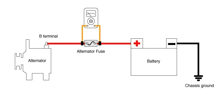
|
| (2)
|
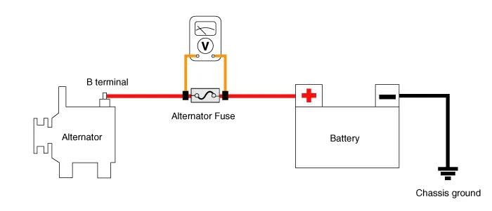
Measure the voltage as shown in the image below.
Standard value (V) : About 0
|
|
| (3)
|
If the alternator fuse blown, below replace the alternator fuse.
| a. |
Turn ignition switch OFF and disconnect the battery negative ( - ) terminal.
|
| b. |
Remove the battery positive ( + ) cable mounting nut .
|
| c. |
Remove the battery positive ( + ) cable.
|
| d. |
Replace the norminal alternator fuse or battery cable.
|
| e. |
Install in the reverse order of removal.
|
|
| (1)
|
Check the battery sensor fuse for continuity .
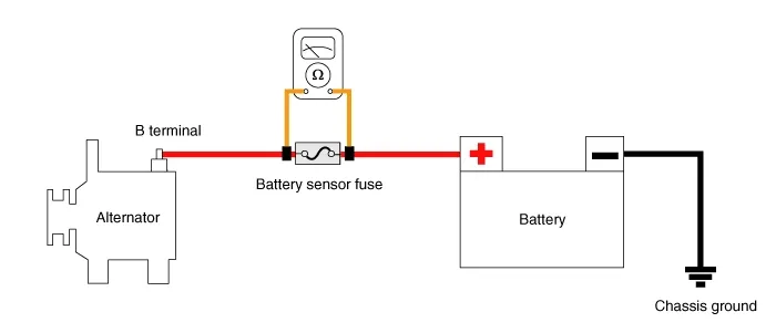
|
| (2)
|
If the alternator fuse blown, replace the battery sensor fuse.
|
| (3)
|
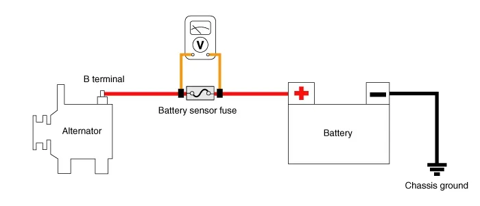
Measure the voltage as shown in the image below.
Standard value (V) : About 0
|
|
|
| 3. |
Inspect Drive Belt
| (1)
|
Visually check the belt for excessive wear, frayed cords etc.
If any defect has been found, replace the drive belt.
|
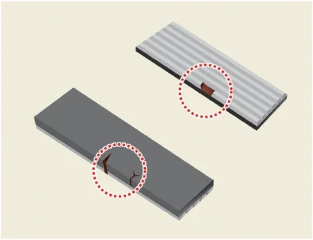
Cracks on the rib side of a belt are considered acceptable. If the belt has chunks missing
from the ribs, it should be replaced.
|
|
|
| 4. |
Drive belt tension measurement and adjustment.
(Refer to Engine Mechanical System - "Drive Belt")
|
| 5. |
Visually Check Alternator Wiring And Listen For Abnormal Noises
| (1)
|
Check that the wiring is in good condition.
|
| (2)
|
Check that there is no abnormal noise from the alternator while the engine is running.
|
|
| 6. |
Check Discharge Warning Light Circuit
| (1)
|
Warm up the engine and then turn it off.
|
| (2)
|
Turn off all accessories
|
| (3)
|
Turn the ignition switch "ON". Check that the discharge warning light is lit.
|
| (4)
|
Start the engine. Check that the light is lit..
If the light does not go off as specified, troubleshoot the discharge light circuit.
|
|
Terminal Tightening State Inspection
|
•
|
Alternator B+ terminal state
|
|
•
|
Alternator B+ terminal tightening nut
|
|
•
|
Battery positive ( + ) terminal state
|
|
•
|
Battery positive ( + ) terminal tightening nut state
|
|
•
|
Battery negative ( - ) terminal state
|
|
•
|
Battery negative ( - ) terminal tightening nut state
|
|
•
|
Battery negative ( - ) terminal mounting bolt tightening state (Chassis ground)
|
|
•
|
Battery sensor negative ( - ) terminal state (With battery sensor)
|
|
•
|
Battery sensor negative ( - ) terminal tightening nut state (With battery sensor)
|
|
•
|
Battery sensor negative ( - ) terminal mounting bolt tightening state (Chassis ground) [With
battery sensor]
|
|
•
|
Engine room fuse & relay box positive ( + ) harness state
|
|
•
|
Engine room fuse & relay box positive ( + ) harness tightening nut state
|
|
•
|
Check the status of ground fault by chassis paint
|
|
| Inspection Component Location |
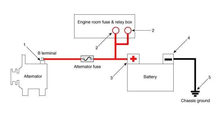
1. Alternator B+ terminal
2. Engine room fuse &
relay box positive ( + ) terminal
3. Battery negative ( + ) terminal
|
4. Battery negative ( - ) terminal
5. Chassis
ground
|
Engine/ Transaxle Ground State Inspection
|
•
|
Mounting bolt tightening state (Chassis)
|
|
•
|
Mounting bolt tightening state (Engine)
|
|
•
|
Check the status of ground fault by chassis paint
|
|
Wiring harness ground state inspection
|
•
|
Mounting bolt tightening state (Chassis)
|
|
•
|
Mounting bolt tightening state (Engine)
|
|
•
|
Check the status of ground fault by chassis paint
|
|
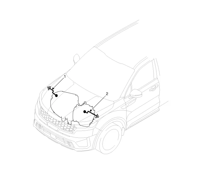
1. Engine ground (Engine ↔ Chassis)
2. Transaxle
ground (Transaxle ↔ Chassis)
|
|
|
Check the ground point.
(Refer to ETM Harness Layout - "Ground Point")
|
Vehicle parasitic current inspection
[Using the Ammeter]
| 1. |
Turn the all electric devices OFF, and then turn the ignition switch OFF.
|
| 2. |
Close all doors except the engine hood, and then lock all doors.
| (1)
|
Disconnect the hood switch connector.
|
| (3)
|
Close the doors or remove the door switches.
|
|
| 3. |
Wait a few minutes until the vehicle’s electrical systems go to sleep mode.
|
For an accurate measurement of a vehicle parasitic current, all electrical systems should go to
sleep mode. (It takes at least one hour or at most one day.) However, an approximate vehicle parasitic
current can be measured after 10 - 20 minutes.
|
|
| 4. |
Connect an ammeter in series between the battery ( - ) terminal and the ground cable, and then disconnect
the clamp from the battery ( - ) terminal slowly.
|
•
|
Be careful that the lead wires of an ammeter do not come off from the battery ( - )
terminal and the ground cable to prevent the battery from being reset. In case the battery is
reset, connect the battery cable again, and then start the engine or turn the ignition switch
ON for more than 10 sec. Repeat the procedure from No. 1.
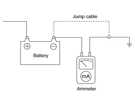
To prevent the battery from being reset during the inspection,
|
| 1) |
Connect a jump cable between the battery ( - ) terminal and the ground cable.
|
| 2) |
Disconnect the ground cable from the battery ( - ) terminal.
|
| 3) |
Connect an ammeter between the battery ( - ) terminal and the ground cable.
|
| 4) |
After disconnecting the jump cable, read the current value of the ammeter.
|
|
|
| 5. |
Read the current value of the ammeter.
|
•
|
If the parasitic current is over the limit value, search for abnormal circuit by removing a fuse
one by one and checking the parasitic current.
|
|
•
|
Reconnect the suspected parasitic current draw circuit fuse only and search for suspected unit by
removing the component connected with the circuit one by one until the parasitic draw drops below
limit value.
|
Limit value (mA) : Below 50 (after 10 - 20 min.)
|
|
[Using the Clamp type Ammeter]
| 1. |
Turn the all electric devices OFF, and then turn the ignition switch OFF.
|
| 2. |
Close all doors except the engine hood, and then lock all doors.
| (1)
|
Disconnect the hood switch connector.
|
| (3)
|
Close the doors or remove the door switches.
|
|
| 3. |
Wait a few minutes until the vehicle’s electrical systems go to sleep mode.
|
For an accurate measurement of a vehicle parasitic current, all electrical systems should go to
sleep mode. (It takes at least one hour or at most one day.) However, an approximate vehicle parasitic
current can be measured after 10 - 20 minutes.
|
|
| 4. |
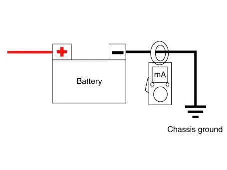
Install the clamp type ammeter on battery negative ( - ) terminal.
|
| 5. |
Read the current value of the ammeter.
|
•
|
If the parasitic current is over the limit value, search for abnormal circuit by removing a fuse
one by one and checking the parasitic current.
|
|
•
|
Reconnect the suspected parasitic current draw circuit fuse only and search for suspected unit by
removing the component connected with the circuit one by one until the parasitic draw drops below
limit value.
|
Limit value (mA) : Below 50 (after 10 - 20 min.)
|
|
Troubleshooting
Symptom
Suspected Area
Correction
Charging warning indicator does not light with ignition switch "ON" and engi...
Specification
Item
Specification
Rated voltage (V, A)
13.5, 150
Speed in use (rpm)
...



 Troubleshooting
 Alternator Specifications
