Kia Sorento: Joint Assembly (Wheel side) Repair procedures - Driveshaft Assembly - Driveshaft and axleKia Sorento: Joint Assembly (Wheel side) Repair procedures

Kia Sorento (MQ4, 2021-2026) Service Manual / Driveshaft and axle / Driveshaft Assembly / Joint Assembly (Wheel side) Repair procedures

Removal
1.
Remove the Front Driveshaft.
(Refer to Driveshaft Assembly - “Front Driveshaft”)
2.
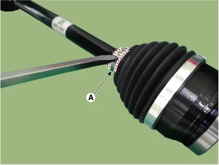
Use a flat-head screw driver to remove the small diameter boot band (A).

Driveshaft and axle — Driveshaft Assembly / Joint Assembly (Wheel side) / Repair procedures / Removal illustration

3.
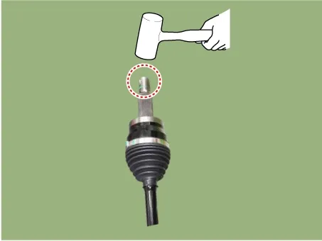
Using a plastic mallet, lower the top of the joint spline 2 - 3 times.

Driveshaft and axle — Driveshaft Assembly / Joint Assembly (Wheel side) / Repair procedures / Removal illustration

Note
•
Be careful not to damage parts when using a plastic hammer.
•
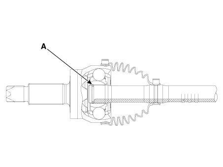
Shock gives the spacing of the circlip (A) fixed to the inside.

Driveshaft and axle — Driveshaft Assembly / Joint Assembly (Wheel side) / Repair procedures / Removal illustration

4.
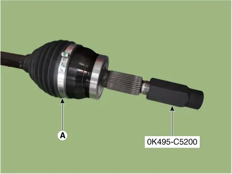
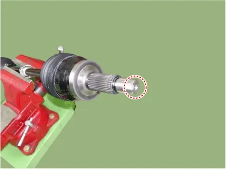
Tighten the SST (0K495-C5200) on the spline of the driveshaft (A).

Driveshaft and axle — Driveshaft Assembly / Joint Assembly (Wheel side) / Repair procedures / Removal illustration

5.
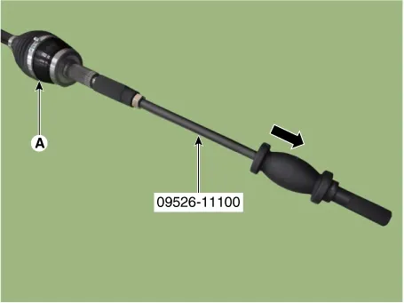
After fixing the driveshaft to the vise, remove the joint assembly (A) using a SST (09526-11100).

Driveshaft and axle — Driveshaft Assembly / Joint Assembly (Wheel side) / Repair procedures / Removal illustration

Note
•
Hit the sliding hammer strongly in the direction of the arrow and remove it at once.
•
If you can't remove it once or twice, it is impossible to remove as circlip is caught inside.
(Replace the driveshaft assembly if it cannot be removed.)
6.
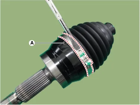
Use a flat-head screw driver to remover to remove the large diameter boot band (A).

Driveshaft and axle — Driveshaft Assembly / Joint Assembly (Wheel side) / Repair procedures / Removal illustration

7.
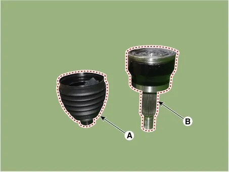
Remove the joint boot (A) and the joint assembly (B).

Driveshaft and axle — Driveshaft Assembly / Joint Assembly (Wheel side) / Repair procedures / Removal illustration

8.
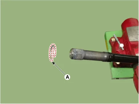
Remove the circlip (A) from the driveshaft.

Driveshaft and axle — Driveshaft Assembly / Joint Assembly (Wheel side) / Repair procedures / Removal illustration

Inspection
1.
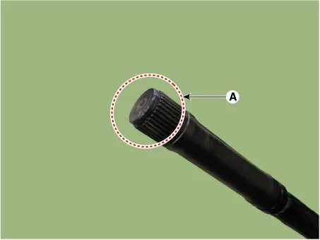
Check spline (A) for damage / wear / crack.

Driveshaft and axle — Driveshaft Assembly / Joint Assembly (Wheel side) / Repair procedures / Inspection illustration

2.
Check the boot for water or foreign objects.
3.
Check joint assembly for damage / wear / crack and rust.
4.
Replace any defective parts.
Installation
Note
•
When assembling, be careful not to let dust and foreign substances enter.
•
Driveshaft joints require special grease, so do not add any other type of grease.
•
Boot bands must use the new one.
1.
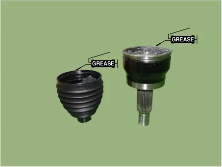
Apply grease within the joint housing and the boot.

Driveshaft and axle — Driveshaft Assembly / Joint Assembly (Wheel side) / Repair procedures / Installation illustration

Note
•
Use the grease supplied with joint kits/boot kits.
•
Driveshaft joints require special grease, so do not add any other type of grease.
•
A certain amount of grease (2-30%) is applied in the boot.
2.
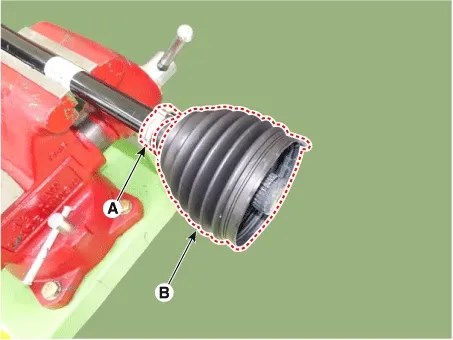
Install the wheel side boot band (A) and boot (B) to the driveshaft.

Driveshaft and axle — Driveshaft Assembly / Joint Assembly (Wheel side) / Repair procedures / Installation illustration

3.
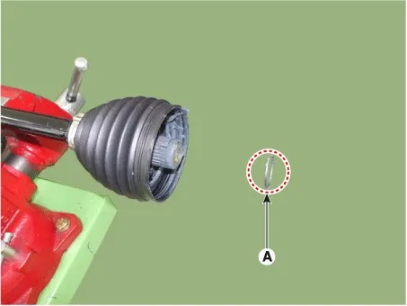
Fit the circlip (A) to the joint.

Driveshaft and axle — Driveshaft Assembly / Joint Assembly (Wheel side) / Repair procedures / Installation illustration

4.
Insert the boot into the joint.
5.
Using a plastic mallet, lower the top of the joint spline 2~3 times.

Driveshaft and axle — Driveshaft Assembly / Joint Assembly (Wheel side) / Repair procedures / Installation illustration

Note
•
Be careful not to damage parts when using a plastic hammer.
•
After installing, the joint assembly and circlip (A) see that it is properly seated.
•
There should be a feeling of squeezing when the joint assembly is pushed and pulled.

Driveshaft and axle — Driveshaft Assembly / Joint Assembly (Wheel side) / Repair procedures / Installation illustration

6.
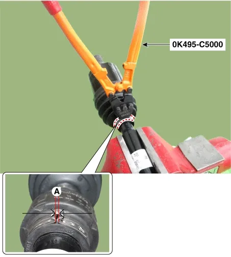
Install the small diameter boot band by using the SST (0K495-C5000).

Clearance (A): 2.0 mm (0.0787 in.) or less

Driveshaft and axle — Driveshaft Assembly / Joint Assembly (Wheel side) / Repair procedures / Installation illustration

7.
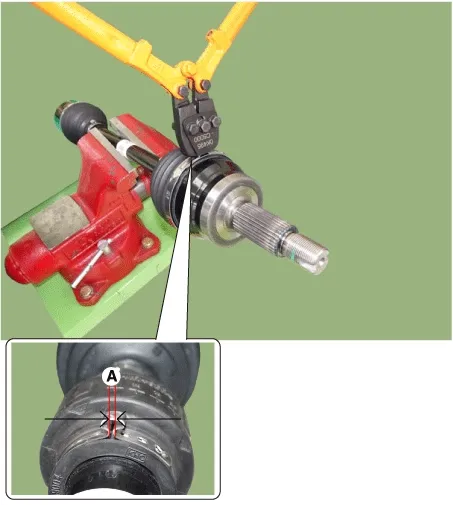
Install the large diameter boot band by using the SST (0K495-C5000).

Clearance (A): 2.0 mm (0.0787 in.) or less

Driveshaft and axle — Driveshaft Assembly / Joint Assembly (Wheel side) / Repair procedures / Installation illustration

Note
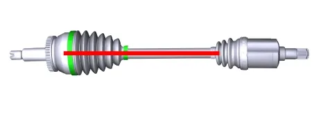
When attaching the small diameter band, fasten it in line by clamping the boot as shown (A).

Driveshaft and axle — Driveshaft Assembly / Joint Assembly (Wheel side) / Repair procedures / Installation illustration

8.
Install the Front Driveshaft.
(Refer to Driveshaft Assembly - “Front Driveshaft”)
Joint Assembly (Wheel side) Components and Components Location

Components 1. Wheel side joint assembly2. Wheel side circlip3. Wheel side boot band4. Wheel side boot 5. Shaft6. Transaxle side boot band7. Transaxle...
Rear Driveshaft Assembly
...
See also:

For best battery service
Keep the battery securely mounted. Keep the battery top clean and dry. Keep the terminals and connections clean, tight, and coated with petroleum jelly or terminal grease. Rinse any spill ...

Integrated memory system: (if equipped)
The integrated memory system for the driver’s seat in your Kia Sorento is a sophisticated convenience feature engineered to store and instantly recall your preferred driving positions with ...

Vehicle handling instructions
As with other vehicles of this type, failure to operate this vehicle correctly may result in loss of control, an accident or vehicle rollover. Specific design characteristics (higher ground clearanc ...

Copyright © www.ksmanual.com 2014-2026 - 0.0525