Kia Sorento: Joint Assembly (Transaxle side) Repair procedures - Driveshaft Assembly - Driveshaft and axleKia Sorento: Joint Assembly (Transaxle side) Repair procedures

Kia Sorento (MQ4, 2021-2026) Service Manual / Driveshaft and axle / Driveshaft Assembly / Joint Assembly (Transaxle side) Repair procedures

Removal
Caution
•
Drive shaft joints require special grease, so do not add any other type of grease.
•
When removing the boot band, the boot band must be brand new.
1.
Remove the Front Driveshaft.
(Refer to Driveshaft Assembly - “Front Driveshaft”)
2.
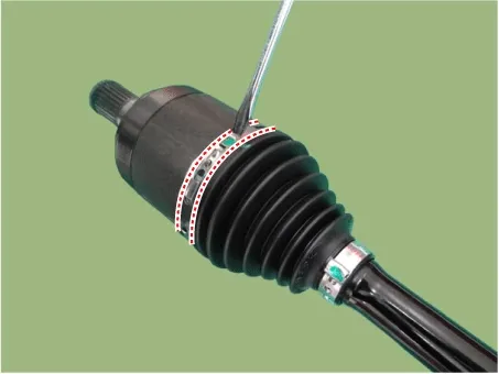
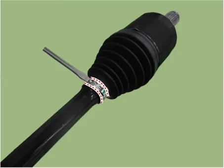
Remove both boot bands from the transaxle side joint.

Driveshaft and axle — Driveshaft Assembly / Joint Assembly (Transaxle side) / Repair procedures / Removal illustration

Driveshaft and axle — Driveshaft Assembly / Joint Assembly (Transaxle side) / Repair procedures / Removal illustration

3.
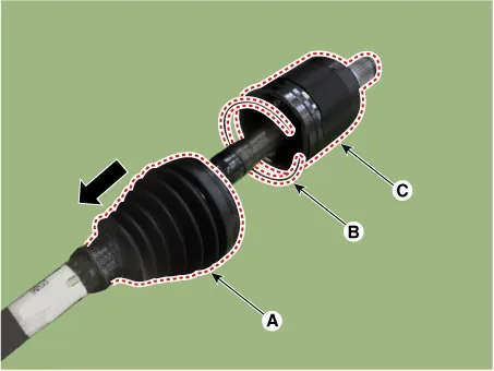
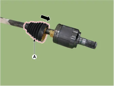
Remove the joint stopper ring (B) and the joint housing (C) after separating the transaxle side joint boot (A) in the direction of the arrow.

Driveshaft and axle — Driveshaft Assembly / Joint Assembly (Transaxle side) / Repair procedures / Removal illustration

4.
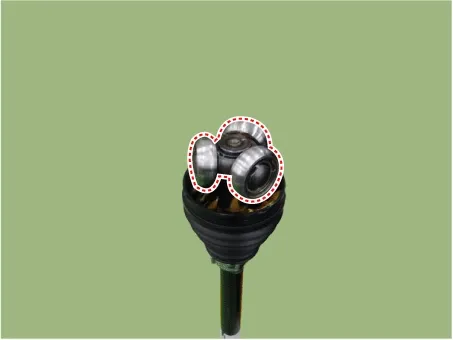
Remove the bearing from the spider assembly.

Driveshaft and axle — Driveshaft Assembly / Joint Assembly (Transaxle side) / Repair procedures / Removal illustration

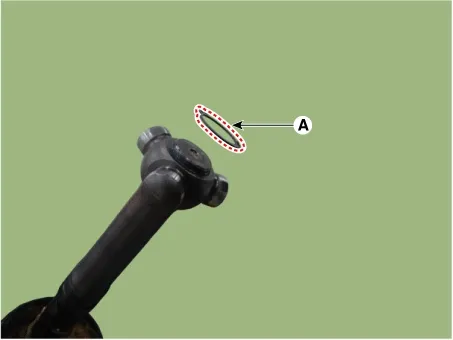
5.
Use the snap ring pliers to remove the snap ring (A).

Driveshaft and axle — Driveshaft Assembly / Joint Assembly (Transaxle side) / Repair procedures / Removal illustration

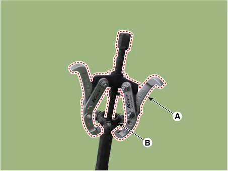
6.
Remove spider assembly (B) from driveshaft using puller (A).

Driveshaft and axle — Driveshaft Assembly / Joint Assembly (Transaxle side) / Repair procedures / Removal illustration

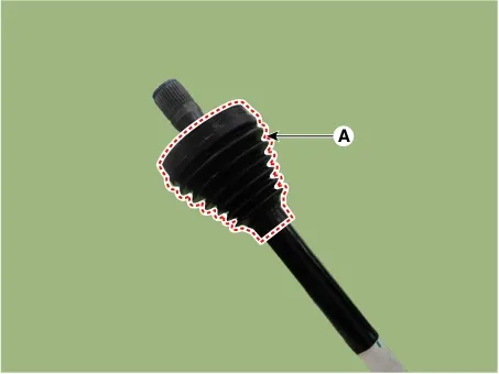
7.
Remove the transaxle side joint boot (A).

Driveshaft and axle — Driveshaft Assembly / Joint Assembly (Transaxle side) / Repair procedures / Removal illustration

8.
Clean the spider assembly and joint housing.
Inspection
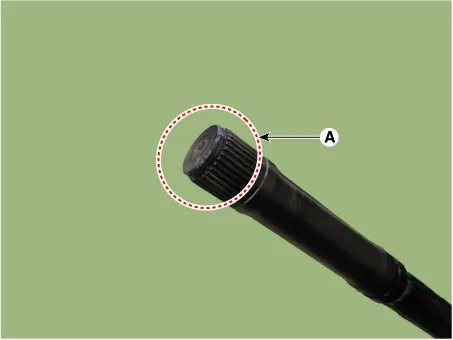
1.
Check spline (A) for damage / wear / crack.

Driveshaft and axle — Driveshaft Assembly / Joint Assembly (Transaxle side) / Repair procedures / Inspection illustration

2.
Check the boot for water or foreign objects.
3.
Check joint assembly for damage / wear / crack and rust.
4.
Replace any defective parts.
Installation
Note
•
When assembling, be careful not to let dust and foreign substances enter.
•
Driveshaft joints require special grease, so do not add any other type of grease.
•
Boot bands must use the new one.
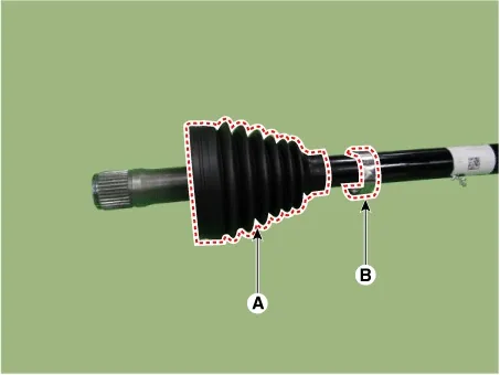
1.
Install the transaxle side boot (A) and boot band (B) on the driveshaft.

Driveshaft and axle — Driveshaft Assembly / Joint Assembly (Transaxle side) / Repair procedures / Installation illustration

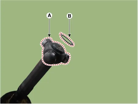
2.
Install it in the order of spider assembly (A) and snap ring (B) in the driveshaft spline.

Driveshaft and axle — Driveshaft Assembly / Joint Assembly (Transaxle side) / Repair procedures / Installation illustration

Note
•
Note the orientation of the spider assembly.
If the spider assembly is not properly oriented, the snap ting will not seat properly.
•
When replacing the joint assembly, assemble using the new parts included in the joint kit.
•
Snap ring must use a new one.
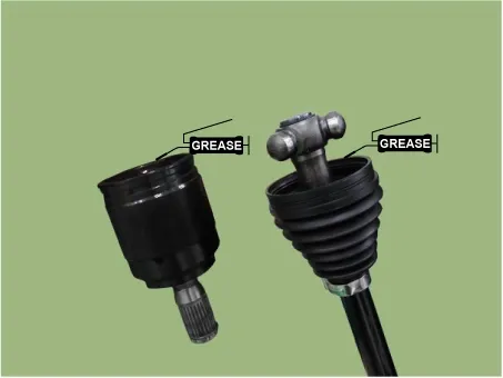
3.
It applies a prescribed grease within the joint housing and the boot.

Driveshaft and axle — Driveshaft Assembly / Joint Assembly (Transaxle side) / Repair procedures / Installation illustration

Note
•
Use the grease supplied with joint kits/boot kits.
•
Driveshaft joints require special grease, so do not add any other type of grease.
•
A certain amount of grease (2-30%) is applied in the boot.
4.
Install the bearing on the spider assembly.

Driveshaft and axle — Driveshaft Assembly / Joint Assembly (Transaxle side) / Repair procedures / Installation illustration

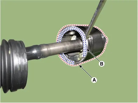
5.
Assemble the transaxle side joint housing (A) to the driveshaft and mount the stopper ring (B).

Driveshaft and axle — Driveshaft Assembly / Joint Assembly (Transaxle side) / Repair procedures / Installation illustration

Note
•
Check that the stopper ring is correctly mounted in the joint housing.
•
Make sure that the joint housing does not come out when pulled out.
6.
Install the boot (A) on the joint housing.

Driveshaft and axle — Driveshaft Assembly / Joint Assembly (Transaxle side) / Repair procedures / Installation illustration

7.
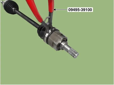
Install the large diameter boot band by using the SST (09495-39100).

Driveshaft and axle — Driveshaft Assembly / Joint Assembly (Transaxle side) / Repair procedures / Installation illustration

8.
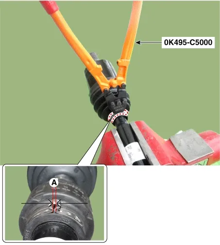
Install the small diameter boot band by using the SST (0K495-C5000).

Clearance (A): 2.0 mm (0.0787 in.) or less

Driveshaft and axle — Driveshaft Assembly / Joint Assembly (Transaxle side) / Repair procedures / Installation illustration

Note
When attaching the small diameter band, fasten it in by clamping the boot as shown (A).

Driveshaft and axle — Driveshaft Assembly / Joint Assembly (Transaxle side) / Repair procedures / Installation illustration

9.
Install the Front Driveshaft.
(Refer to Driveshaft Assembly - “Front Driveshaft”)
Joint Assembly (Transaxle side) Components and Components Location

Components 1. Wheel side joint assembly2. Wheel side circlip3. Wheel side boot band4. Wheel side boot 5. Shaft6. Transaxle side boot band7. Transaxle...
Joint Assembly (Wheel side) Components and Components Location
Components 1. Wheel side joint assembly2. Wheel side circlip3. Wheel side boot band4. Wheel side boot 5. Shaft6. Transaxle side boot band7. Transaxle...
See also:

Small pocket (for 6 passenger vehicle)
6-passenger models feature a compact utility pocket built directly into the side of the 2nd-row seat cushion, offering handy storage for small items like phones, keys, or media players. ...

Installation
   ...

Curtain Airbag (CAB) On Vehicle Inspection. Curtain Airbag (CAB) Troubleshooting
Curtain Airbag (CAB) On Vehicle Inspection On Vehicle Inspection Diagnostic with KDS 1. The center side ...

Copyright © www.ksmanual.com 2014-2026 - 0.0556