Kia Sorento: Integrated Thermal Management Module (ITM) Repair procedures - Cooling System - Engine Mechanical SystemKia Sorento: Integrated Thermal Management Module (ITM) Repair procedures

Kia Sorento (MQ4, 2021-2026) Service Manual / Engine Mechanical System / Cooling System / Integrated Thermal Management Module (ITM) Repair procedures

Removal and Installation
Integrated Thermal Management Module (ITM)
Caution
•
Be careful not to allow the static electricity or any voltage is applied to integrated thermal management module (ITM).
•
Keep away the magnetic objects (Ex. magnet) from the integrated thermal management module (ITM).
•
When disconnecting the integrated thermal management module (ITM) connector, recheck that the engine and all power supplies are shut OFF.
•
When connecting the integrated thermal management module (ITM) connector, moisture and oil in the connector must be completely removed and foreign materials should not enter.
•
When replacing the integrated thermal management module (ITM) connector, be sure to use the specified connector.
1.
Disconnect the battery negative ( - ) terminal.
2.
Remove the engine cover.
(Refer to Engine And Transaxle Assembly - "Engine Cover")
3.
Remove the air intake hose.
(Refer to Intake And Exhaust System - "Air Cleaner")
4.
Remove the engine room under cover.
(Refer to Engine And Transaxle Assembly - "Engine Room Under Cover")
5.
Drain the engine coolant.
(Refer to Cooling System - "Coolant")
6.
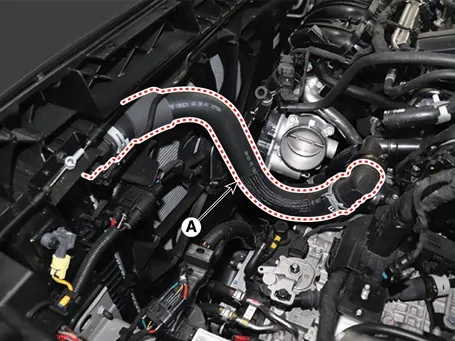
Disconnect the radiator upper hose quick connector (A).

Engine Mechanical System — Cooling System / Integrated Thermal Management Module (ITM) / Repair procedures / Removal and Installation illustration

7.
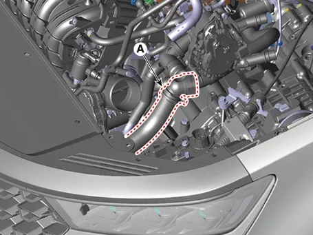
Disconnect the radiator lower hose quick connector (A).

Engine Mechanical System — Cooling System / Integrated Thermal Management Module (ITM) / Repair procedures / Removal and Installation illustration

8.
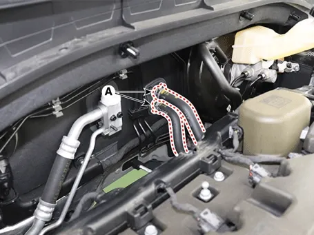
Disconnect the heater hoses (A).

Engine Mechanical System — Cooling System / Integrated Thermal Management Module (ITM) / Repair procedures / Removal and Installation illustration

9.
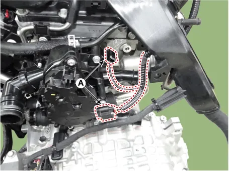
Disconnect the integrated thermal management module (ITM) connector (A).

Engine Mechanical System — Cooling System / Integrated Thermal Management Module (ITM) / Repair procedures / Removal and Installation illustration

10.
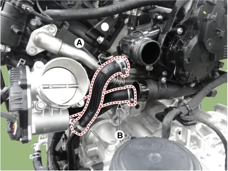
Disconnect the ATF warmer hose (A) and oil cooler hose (B).

Engine Mechanical System — Cooling System / Integrated Thermal Management Module (ITM) / Repair procedures / Removal and Installation illustration

11.
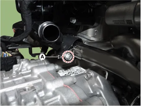
Remove the water inlet pipe mounting bolt (A).

Tightening torque :
9.8 - 11.8 N·m (1.0 - 1.2 kgf·m , 7.2 - 8.7 lb·ft)

Engine Mechanical System — Cooling System / Integrated Thermal Management Module (ITM) / Repair procedures / Removal and Installation illustration

12.
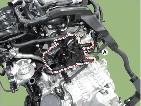
Remove the integrated thermal management module (ITM) (A).

Tightening torque :
9.8 - 11.8 N·m (1.0 - 1.2 kgf·m , 7.2 - 8.7 lb·ft)

Engine Mechanical System — Cooling System / Integrated Thermal Management Module (ITM) / Repair procedures / Removal and Installation illustration

Note
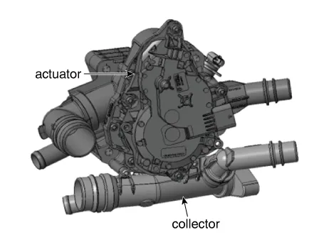
Do not dismantle the actuator and collector because integrated thermal management module (ITM) is supplied as an assembly unit.

Engine Mechanical System — Cooling System / Integrated Thermal Management Module (ITM) / Repair procedures / Removal and Installation illustration

Note
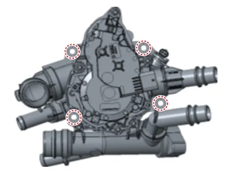
When removing the integrated thermal management module (ITM), remove the bolts and nuts shown in the below.

Engine Mechanical System — Cooling System / Integrated Thermal Management Module (ITM) / Repair procedures / Removal and Installation illustration

13.
Install in the reverse order of removal.
Note
•
Always use the new integrated thermal management module (ITM) rubber gasket.
•
Always use the new water inlet pipe O-ring.
•
When installing the water inlet pipe, apply anti-freeze or soapy water to O-ring.
14.
Fill with engine coolant.
(Refer to Cooling System - "Coolant")
Note
The coolant must be injected according to the integrated thermal management module (ITM) coolant filling method.
15.
Start engine and check for leaks.
16.
Recheck engine coolant level.
Water inlet pipe
1.
Disconnect the battery negative ( - ) terminal.
2.
Remove the engine cover.
(Refer to Engine And Transaxle Assembly - "Engine Cover")
3.
Remove the air intake hose.
(Refer to Intake And Exhaust System - "Air Cleaner")
4.
Remove the battery and battery tray.
(Refer to Engine Electrical System - "Battery")
5.
Remove the engine room under cover.
(Refer to Engine And Transaxle Assembly - "Engine Room Under Cover")
6.
Drain engine coolant.
(Refer to Cooling System - "Coolant")
7.
Remove the integrated thermal management module (ITM).
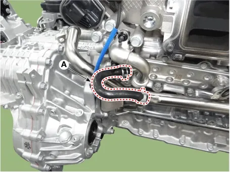
8.
Disconnect the water return hose (A).

Engine Mechanical System — Cooling System / Integrated Thermal Management Module (ITM) / Repair procedures / Removal and Installation illustration

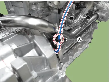
9.
Remove the crankshaft position sensor (CKPS) wiring clip (A).

Engine Mechanical System — Cooling System / Integrated Thermal Management Module (ITM) / Repair procedures / Removal and Installation illustration

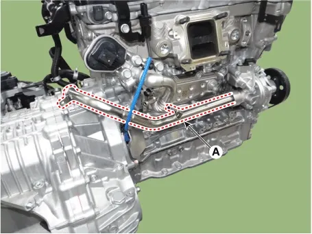
10.
Remove the water inlet pipe (A).

Engine Mechanical System — Cooling System / Integrated Thermal Management Module (ITM) / Repair procedures / Removal and Installation illustration

11.
Install in the reverse order of removal.
Note
•
Always use the new water inlet pipe O-ring.
•
When installing the water inlet pipe, apply anti-freeze or soapy water to O-ring.
12.
Fill with engine coolant.
(Refer to Cooling System - "Coolant")
Note
The coolant must be injected according to the integrated thermal management module (ITM) coolant filling method.
13.
Start engine and check for leaks.
14.
Recheck engine coolant level.
Integrated Thermal Management Module (ITM) Components and Components Location. Integrated Thermal Management Module (ITM) Description and Operation

Integrated Thermal Management Module (ITM) Components and Components Location Components 1. Integrated thermal management module (ITM)2. W...
Water pump Components and Components Location
Components 1. Water pump pulley2. Water pump 3. Water pump gasket4. Water pump housing5. Water pump housing gasket...
See also:

Front Strut Assembly Removel
1. Remove the front wheel and tire (A) from front hub . Tightening torque: 88.2 ~ 107.8 N.m (9.0 ~ 11.0 kgf.m, 65.0 ~ 79.5 lb-ft) ...

Front Impact Sensor (FIS) On Vehicle Inspection
On Vehicle Inspection Diagnostic with KDS 1. The front impact sensor can be more quickly diagnosed for ...

Specification
Tightening Torque Tightening Torque Seat Belt Pretensioner (BPT) Front Seat Belt Pretensioner (BPT) Item N·m ...

Copyright © www.ksmanual.com 2014-2026 - 0.0443