
 Kia Sorento: Intake Manifold Repair procedures
Kia Sorento (MQ4, 2021-2026) Service Manual / Engine Mechanical System / Intake And Exhaust System / Intake Manifold Repair procedures
| Removal and Installation |
| 1. |
Disconnect the battery negative ( - ) terminal.
|
| 2. |
Remove the engine cover.
(Refer to Engine And Transaxle Assembly - "Engine Cover")
|
| 3. |
Remove the air duct and air cleaner assembly.
(Refer to Intake And Exhaust System - Air Cleaner")
|
| 4. |
Remove the engine room under cover.
(Refer to Engine And Transaxle Assembly - "Engine Room Under
Cover")
|
| 5. |
Remove the oil filter & oil cooler.
(Refer to Lubrication System - "Oil Filter & Oil
Cooler")
|
| 6. |
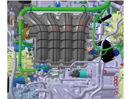
Remove the engine wiring connectors and harness clamps around the intake manifold and then remove the
connector brackets and wiring protector.
|
| 7. |
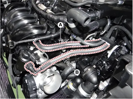
Disconnect the vacuum hose (A) and purge control solenoid valve (PCSV) hose (B).
|
| 8. |
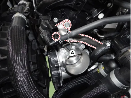
Loosen the EGR cooler pipe C mounting bolts (A) and obtain working space to remove the intake manifold.
|
| 9. |
Remove the electronic throttle control (ETC) module.
(Refer to Engine Control/Fuel System - "ETC (Electronic Throttle
Control) system")
|
| 10. |
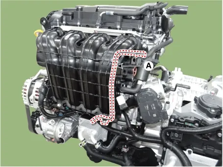
Remove the bleeder pipe (A).
|
| 11. |
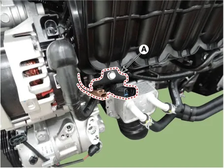
Remove the wiring bracket (A).
|
| 12. |
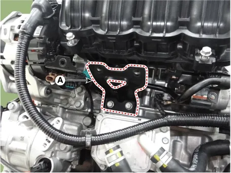
Remove the intake manifold stay (A).
|
| 13. |
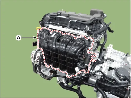
Remove the intake manifold (A) with the gasket.
|

| 14. |
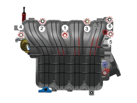
Install in the reverse order of removal.
|
Components
1. Intake manifold2. Intake manifold gasket3.
Intake manifold stay4. Electronic Throttle Contorl (ETC)
5. Electronic Throttle Contorl (ETC...
 Intake Manifold Components and Components Location
Components
1. Exhaust manifold 2. Exhaust manifold gasket
3. Exhaust manifold stay...
 Exhaust Manifold Components and Components Location
See also:
SS-A Solenoid Valve (SS-A_ON/OFF) Description and Operation
Description
•
SS-A solenoid valve is ON/OFF type.
•
...
Fluid Component Location
1. ATF Injection hole(eyebolt)
2. Oil level plug
3. Oil drain plug
...
AC Inverter Oultet Removal
1.
Disconnect the negative (-) battery terminal.
2.
Remove the rear console cover.
(Refer to Body - "Console")
...
Manuals list
- Kia Sorento MQ4 2021-2026 Owners Manual
- Kia Sorento XM 2011-2015 Owners Manual
- Kia Sorento XM 2011-2015 Service Manual

Copyright © www.ksmanual.com 2014-2026 - 0.049