 Kia Sorento: High Pressure Fuel Pump Removal
Second Generation XM (2011-2025) / Kia Sorento XM 2011-2025 Service Manual / Engine Control / Fuel System / Fuel Delivery System / High Pressure Fuel Pump Removal
In case of removing the high pressure fuel pump, high pressure
fuel pipe, delivery pipe, and injector, there may be injury caused by
leakage of the high pressure fuel. So donŌĆÖt do any repair work right
after engine stops.
|
| 1. |
Turn the ignition switch OFF and disconnect the battery negative
(-) cable.
|
| 2. |
Release the residual pressure in fuel line.
(Refer to the Fuel Delivery System - Repair Procedures - "Release
Residual Pressure in Fuel Line")
|
| 3. |
Remove the air cleaner and the air intake hose
(Refer to Engine Mechanical System - ŌĆ£Intake And Exhaust SystemŌĆØ)
|
| 4. |
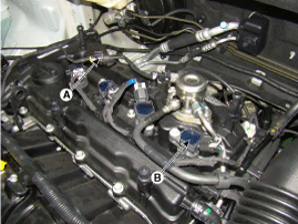
Disconnect the fuel pressure control valve connector (A).
|
| 5. |
Remove the ignition coil (B).
|
| 6. |
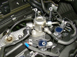
Disconnect the fuel feed tube quick-connector (A).
|
| 7. |
Remove the high pressure fuel pipe.
|
| 8. |
Remove the installation bolts (E), and then remove the high pressure
fuel pump from the cylinder head assembly.
|
 Delivery Pipe Installation
ŌĆó
Install the component with the specified torques.
...
 High Pressure Fuel Pump Installation
ŌĆó
Be sure to check the low pressure fuel hose quick-connector
(A) is completely connec ...
See also:
Component Location
1. Windshield wiper arm & blade
2. Wiper & washer switch
3. Windshield washer hose
4. Windshield wiper motor & linkage
5. Washer motor
6. Washer reservoir
...
Roof rack (if equipped)
If the vehicle has a roof rack, you can load cargo on top of your vehicle.
✽ NOTICE
If the vehicle is equipped with a sunroof, be sure not to position cargo onto
the roof rack in such a wa ...
Removal
ŌĆó
DONŌĆÖT remove the camshaft position sensor while the engine
is running or right aft ...
Copyright ® www.ksmanual.com 2014-2025


