
 Kia Sorento: Headlamps Repair Procedures
| Removal |
| 1. |
Remove the front bumper assembly.
(Refer to Body - "Front Bumper Assembly")
|
| 2. |
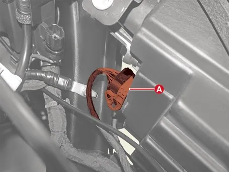
Disconnect the headlamp connector (A).
|
| 3. |
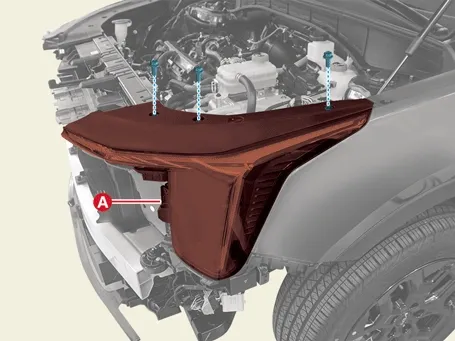
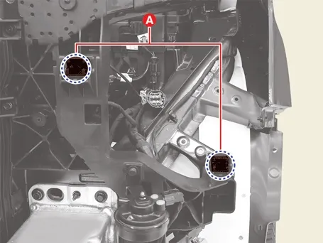
Remove the headlamp (A) removing the bolt.
|

| Installation |
| 1. |
Install in the reverse order of removal.
|
| Replacement |
| 1. |
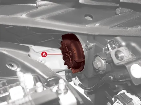
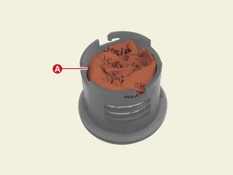
Remove the dust cap (A).
|
| 2. |
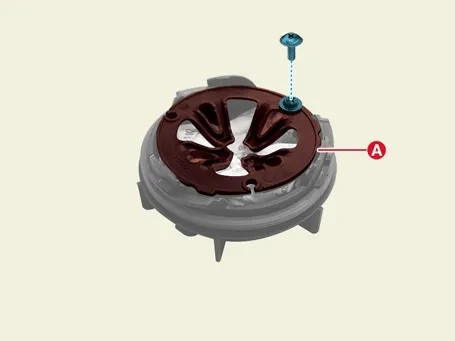
Remove the absorbent bracket (A) after removing the screw.
|
| 3. |
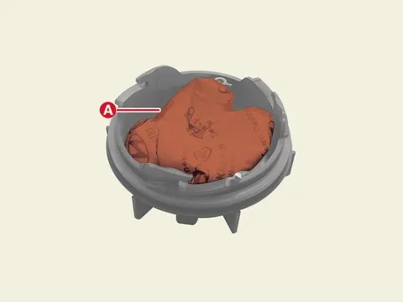
Replace the absorbent.
|
| 1. |
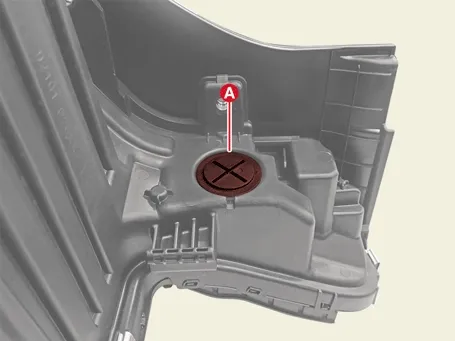
Remove the dust cap (A).
|
| 2. |
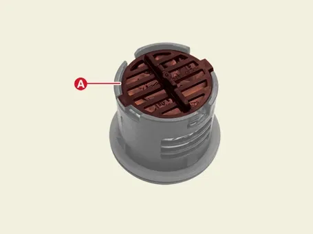
Remove the absorbent bracket (A).
|
| 3. |
Replace the absorbent.
|
| Adjustment |
| 1. |
Inflate the tires to the specified pressure and remove any loads from the vehicle except the driver, spare
tire, and tools.
|
| 2. |
The vehicle should be placed on a flat floor.
|
| 3. |
Check if there is something wrong with the suspension spring.
|
| 4. |
Clean the headlamp lens.
|
| 5. |
Draw vertical lines (Vertical lines passing through respective headlamp centers) and a horizontal line
(Horizontal line passing through center of headlamps) on the screen.
|
| 6. |
With the headlamp and battery in normal condition, aim the headlamps so the brightest portion falls on the
horizontal and vertical lines.
|
| 7. |
Accuracy check of measuring instruments.
|
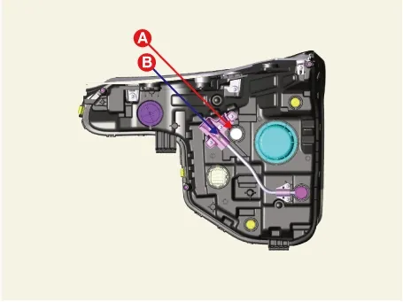
A : Vertical (High/Low beam)
B : Horizontal (High/Low beam)
|

|
Standard |
Option |
|
|
|
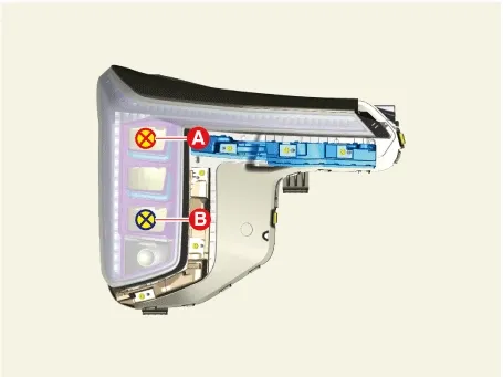
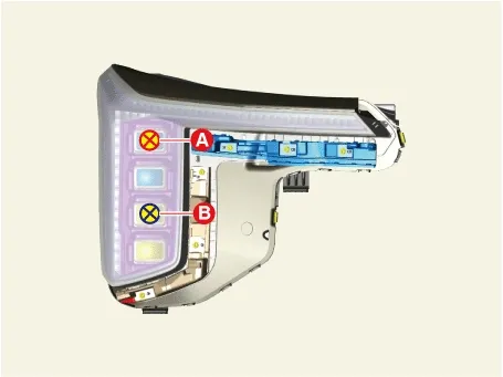
A : Low beam
B : High beam
|
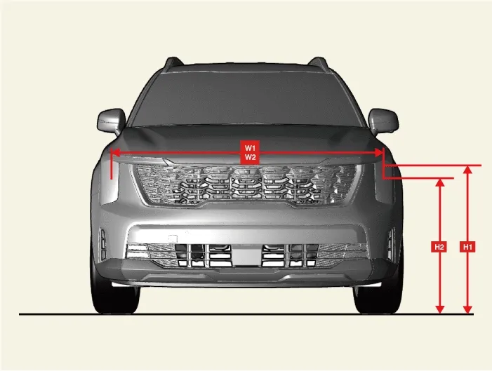
H1 : Height between the headlamps bulb center and ground (Low beam)
H2 : Height between the headlamps bulb center and ground (High beam)
W1 : Distance between the headlamp bulb center (Low beam)
W2 : Distance between the headlamp bulb center (High beam)
|
| Vehicle Condition |
H1 |
H2 |
W1 |
W2 |
Possible Cause |
| Empty |
897 (35.3149) |
780 (30.7086) |
1,584 (62.3622) |
1,584 (62.3622) |
ALL DIM in mm (in.) |
| 1 person on-board |
890 (35.0393) |
773 (30.4330) |
| Vehicle Condition |
H1 |
H2 |
W1 |
W2 |
Possible Cause |
| Empty |
900 (35.4330) |
778 (30.6299) |
1,578 (62.1259) |
1,578 (62.1259) |
ALL DIM in mm (in.) |
| 1 person on-board |
893 (35.1574) |
771 (30.3543) |
| 1. |
If a headlight leveling device is installed, set the headlight leveling device switch to 0.
|
| 2. |
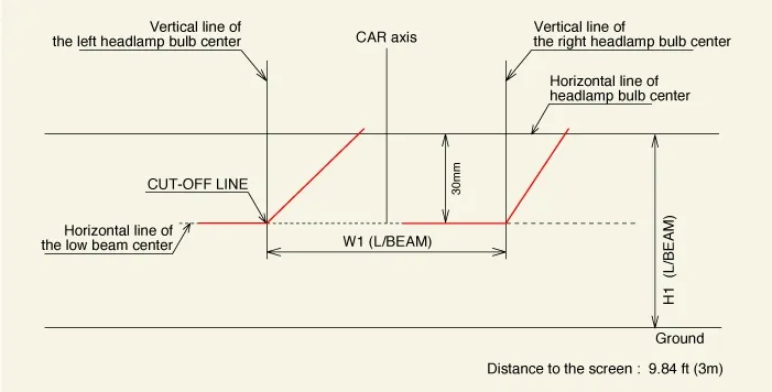
Turn the low beam on without driver aboard.
The low beam cut-off line should be projected as shown in the picture.
|
| 3. |
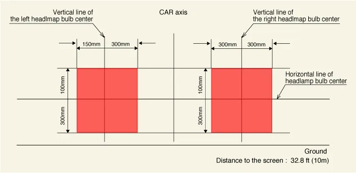
Turn the high beam on without driver aboard.
|
| 4. |
The hot zone should be projected in the allowable range shown in the picture.
|
 Glove Box Lamp Repair Procedures
 High Mounted Stop Lamp Repair Procedures
See also:
Engine Control Module (ECM) Adjustment
Adjustment
...
Paddle Shifter Switch Repair procedures
Removal
1.
Disconnect the battery negative ( - ) terminal.
2.
Remove the drive ...
TPMS Sensor Inspection
Inspection
Inspect After Installing Tire Pressure Sensor
1.
The seal washers must be compressed against the outer surface of the rim ...
Manuals list
- Kia Sorento MQ4 2021-2026 Owners Manual
- Kia Sorento XM 2011-2015 Owners Manual
- Kia Sorento XM 2011-2015 Service Manual
