Kia Sorento: Fuel Pump & Tube Assembly Removal and Installation - Fuel Delivery System - Engine Control / Fuel SystemKia Sorento: Fuel Pump & Tube Assembly Removal and Installation

Kia Sorento (MQ4, 2021-2026) Service Manual / Engine Control / Fuel System / Fuel Delivery System / Fuel Pump & Tube Assembly Removal and Installation

Removal
1.
Remove the fuel pump module.
(Refer to Fuel Delivery System - "Fuel Pump Module")
2.
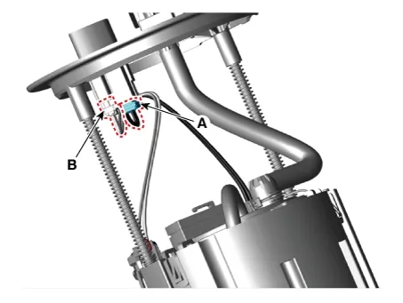
Disconnect the fuel pump motor connector (A) and fuel sender connector (B).

Engine Control / Fuel System — Fuel Delivery System / Fuel Pump & Tube Assembly / Removal and Installation / Removal illustration

3.
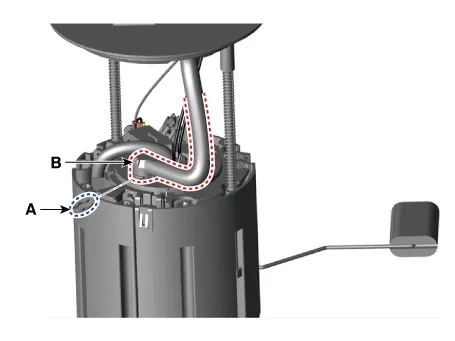
Remove the fuel feed tube quick-connector (B) after removing the clip (A).

Engine Control / Fuel System — Fuel Delivery System / Fuel Pump & Tube Assembly / Removal and Installation / Removal illustration

4.
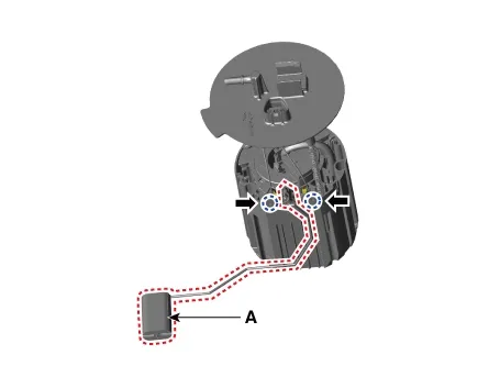
Remove the fuel sender assembly (A) after pushing the hooks in the direction of the arrows.

Engine Control / Fuel System — Fuel Delivery System / Fuel Pump & Tube Assembly / Removal and Installation / Removal illustration

5.
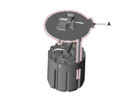
Remove the stopper (A).

Engine Control / Fuel System — Fuel Delivery System / Fuel Pump & Tube Assembly / Removal and Installation / Removal illustration

6.
Remove the fuel pump plate & bracket (A).

Engine Control / Fuel System — Fuel Delivery System / Fuel Pump & Tube Assembly / Removal and Installation / Removal illustration

7.
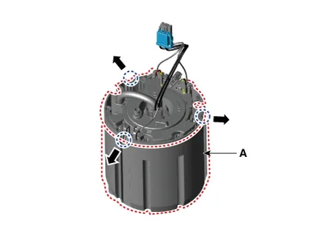
Remove the reservoir cup (A) after pulling the hooks in the direction of the arrows.

Engine Control / Fuel System — Fuel Delivery System / Fuel Pump & Tube Assembly / Removal and Installation / Removal illustration

8.
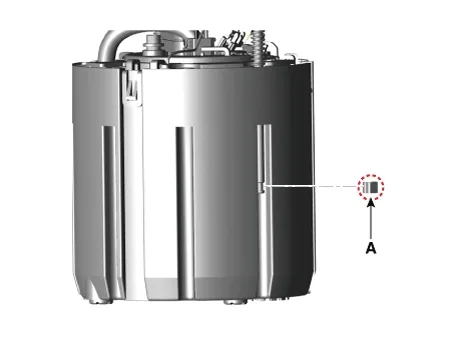
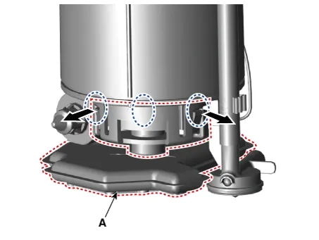
Remove the pump filter (A) after pulling the hooks in the direction of the arrows.

Engine Control / Fuel System — Fuel Delivery System / Fuel Pump & Tube Assembly / Removal and Installation / Removal illustration

9.
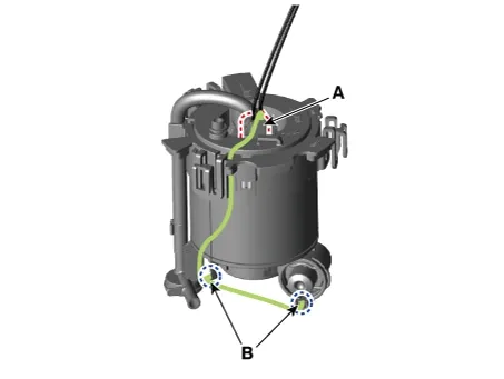
Remove the wiring from the fuel filter after disconnecting the fuel pump connector (A) and ground (B).

Engine Control / Fuel System — Fuel Delivery System / Fuel Pump & Tube Assembly / Removal and Installation / Removal illustration

10.
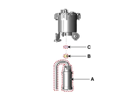
Remove the O-ring (B) and spacer (C) after removing the fuel pump & tube (A).

Engine Control / Fuel System — Fuel Delivery System / Fuel Pump & Tube Assembly / Removal and Installation / Removal illustration

Installation
1.
Install in the reverse order of removal.
Note
•
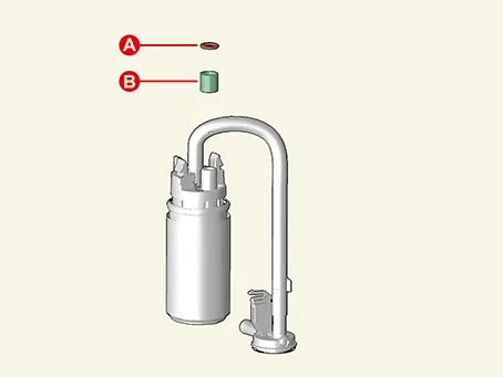
Be careful not to miss the O-ring (A) and the spacer (B) or change the order when assembling the fuel pump.

Engine Control / Fuel System — Fuel Delivery System / Fuel Pump & Tube Assembly / Removal and Installation / Installation illustration

•
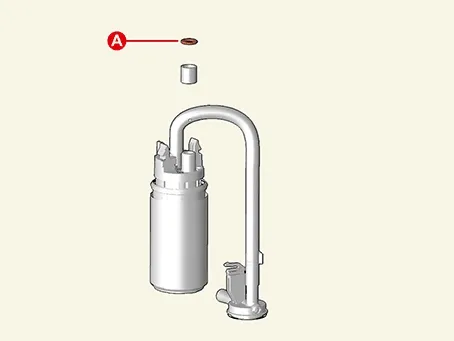
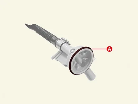
Be careful not to cause damage to O-ring (A) when assembling the fuel pump.

Engine Control / Fuel System — Fuel Delivery System / Fuel Pump & Tube Assembly / Removal and Installation / Installation illustration

•
Correctly install the fuel pump motor and the fuel filter during installation.
•
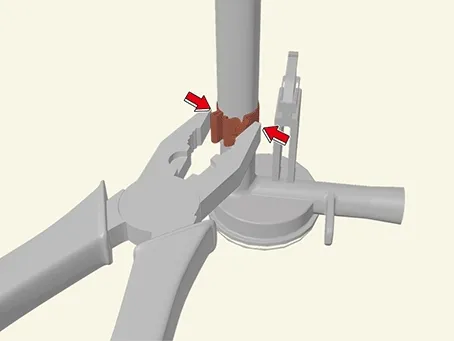
Make sure the hook is correctly fastened when assembling the fuel pump hose clamp.

Engine Control / Fuel System — Fuel Delivery System / Fuel Pump & Tube Assembly / Removal and Installation / Installation illustration

•
Correctly install the fuel filter and the prefilter during installation.
•
Ensure the fuel tube is not twisted when installing the assist pump bracket onto the fuel filter.
•
Be careful not to miss the assist pump O-ring when assembling the reservoir cup.

Engine Control / Fuel System — Fuel Delivery System / Fuel Pump & Tube Assembly / Removal and Installation / Installation illustration

•
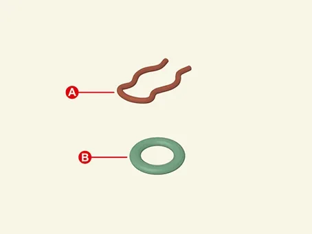
Be careful not to miss the clip (A) and the O-ring (B) when assembling the plate cover assembly.

Engine Control / Fuel System — Fuel Delivery System / Fuel Pump & Tube Assembly / Removal and Installation / Installation illustration

•
Be careful not to cause damage to the O-ring (A) when assembling the plate cover assembly.

Engine Control / Fuel System — Fuel Delivery System / Fuel Pump & Tube Assembly / Removal and Installation / Installation illustration

•
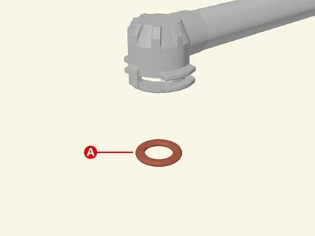
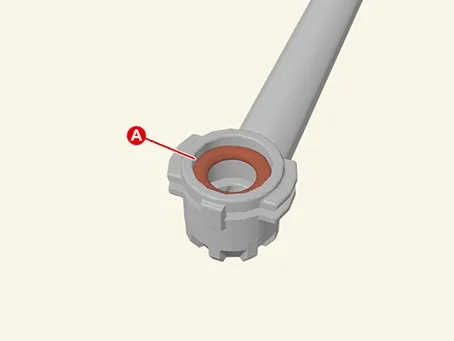
When assembling the plate cover assembly, O-ring (A) can be attached to the fuel supply hose connector.

Engine Control / Fuel System — Fuel Delivery System / Fuel Pump & Tube Assembly / Removal and Installation / Installation illustration

2.
Check for leakage the fuel after installation.
Fuel Pump & Tube Assembly Components and Components Location

Components 1. Clip2. Stopper3. Plate Assembly4. O-Ring5. Fuel Sender Assembly6. Reservoir Cup7. Clip8. Fuel Pressure Regulator 9. Fuel Pump Wiring10....
Fuel Pump Module Specifications. Fuel Pump Module Components and Components Location
Fuel Pump Module Specifications Specification Item Specification Current (A) Maximum 8.5 ...
See also:

Side Impact Sensor (SIS) Description
Side Impact Sensor (SIS) system consists of two Front-SIS which are installed at each center of the front door module (LH and RH) and two Rear-SIS which are installed at each rear pillar near ...

Paddle Shifter Switch Repair procedures
Removal 1. Disconnect the battery negative ( - ) terminal. 2. Remove the drive ...

General
1. Basically, all measurements in this manual are taken with a tracking gauge. 2. When a measuring tape is used, check to be sure there is ...

Copyright © www.ksmanual.com 2014-2026 - 0.0524