
 Kia Sorento: Fuel Pump Module Removal and Installation
Kia Sorento (MQ4, 2021-2026) Service Manual / Engine Control / Fuel System / Fuel Delivery System / Fuel Pump Module Removal and Installation
| Special Service Tool |
| Tool Name / Number |
Illustration |
Description |
|
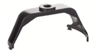
Fuel pump plate cover wrench 09310 - B8100 |
|
Removing and installing fuel pump plate cover |
| Removal |
| 1. |
Release the residual pressure in fuel line.
(Refer to Fuel Delivery System - "Release Residual Pressure in Fuel
Line")
|
| 2. |
Remove the second seat cution.
(Refer to Body - "Rear Seat Assembly")
|
| 3. |
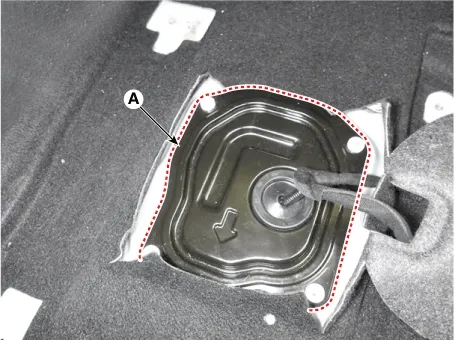
Remove the fuel pump service cover (A).
|
| 4. |
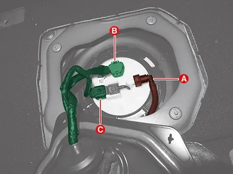
Disconnect the connectors (A, B, C) from the fuel pump.
A : Fuel injection tube quick-connector
B : Fuel pump connector
C : Fuel tank pressure sensor connector
|
| 5. |
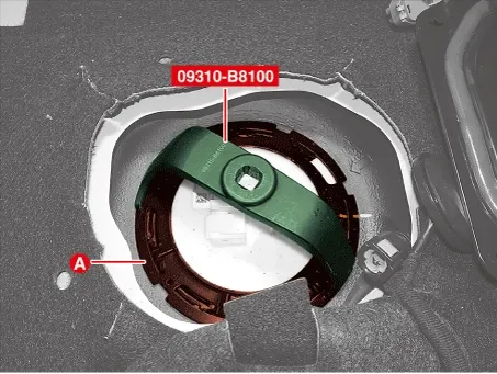
Remove the fuel pump module after removing the plate cover (A) by using a SST (09310 - B8100).
Proper Use of SST and Safe Working Posture for Removing the Tightly Fastened Plate Cover (Play ▶)

Notes When Refering Video
This video helps recognize potential hazards in advance and ensures procedures are performed correctly when
safety precautions are required or when failure to follow steps or procedural errors could affect driving
safety.
|

| Installation |
| 1. |
Install in the reverse order of removal.
|
| 2. |
Check for leakage the fuel after installation.
|
On Vehicle Inspection
1.
The engine control system can be more quickly diagnosed for problems with the KDS. (Refer to "DTC
guide")
...
 Fuel Pump Module On Vehicle Inspection
Fuel Sender Specifications
Specification
Position
Resistance (Ω)
Capacity [ℓ (U.S.gal., U.S.qt., Imp.q...
 Fuel Sender Specifications. Fuel Sender Components and Components Location
See also:
Power Tailgate Unit Circuit Diagram
...
Front Bumper Beam Assembly Repair Procedures
Removal and Installation
Front Bumper Beam
1.
Remove the front bumper assembly.
(Refer to Bumper (Front) - "Front Bumpe ...
Mode Control Actuator Inspection
Inspection
1.
IG OFF.
2.
Disconnect the mode control actuator connector.
...
Manuals list
- Kia Sorento MQ4 2021-2026 Owners Manual
- Kia Sorento XM 2011-2015 Owners Manual
- Kia Sorento XM 2011-2015 Service Manual

Copyright © www.ksmanual.com 2014-2026 - 0.0532