
 Kia Sorento: Filler-Neck Assembly Removal and Installation
Kia Sorento (MQ4, 2021-2026) Service Manual / Engine Control / Fuel System / Fuel Delivery System / Filler-Neck Assembly Removal and Installation
| Removal |
| 1. |
Disconnect the battery negative ( - ) terminal.
|
| 2. |
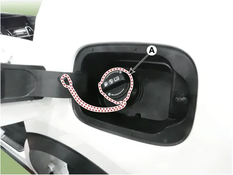
Open the fuel filler cap (A) by turning it in the counterclockwise.
|
| 3. |
Remove the rear wheel guard.
(Refer to Body - "Rear Wheel Guard")
|
| 4. |
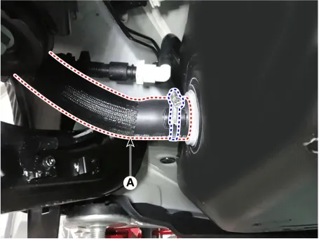
Disconnect the fuel filler hose (A) by removing the clamp.
|
| 5. |
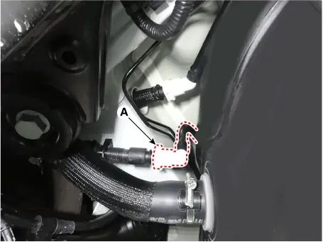
Disconnect the leveling quick-connector (A).
|
| 6. |
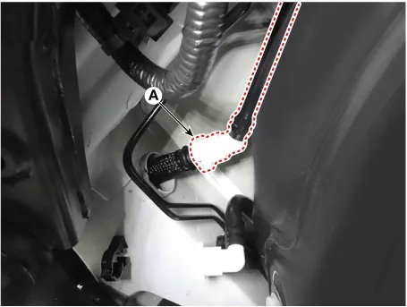
Disconnect the leveling quick-connector (A).
|
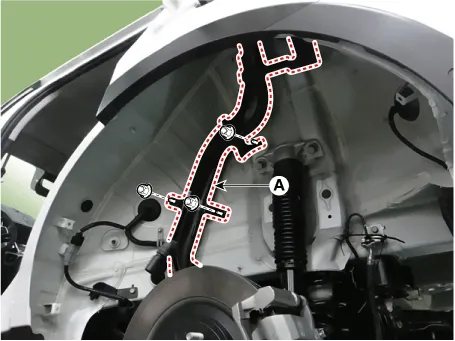
| 7. |
Remove the filler-neck assembly (A) after removing the mounting nuts.
|
| Installation |
| 1. |
Install in the reverse order of removal.
|

Components
1. Filler-Neck Assembly...
 Filler-Neck Assembly Components and Components Location
Components
1. Clip2. Stopper3. Plate Assembly4.
O-Ring5. Fuel Sender Assembly6. Reservoir Cup7. Clip8. Fuel Pressure Regulator
9. Fuel Pump Wiring10....
 Fuel Filter Components and Components Location
See also:
Output Speed Sensor Removal
1.
Remove the valve body assembly.
(Refer to Hydraulic System - "Valve Body")
2.
Disconnect the input & output speed senso ...
Rear Blower Resister Inspection
1.
Measure terminal-to-terminal resistance of the blower resistor.
2.
If the measured resistance is not within specification, the blower
re ...
Manuals list
- Kia Sorento MQ4 2021-2026 Owners Manual
- Kia Sorento XM 2011-2015 Owners Manual
- Kia Sorento XM 2011-2015 Service Manual

Copyright © www.ksmanual.com 2014-2026 - 0.0637