
 Kia Sorento: ESC Control Unit Repair procedures
Kia Sorento (MQ4, 2021-2026) Service Manual / Brake System / Electronic Stability Control (ESC) / ESC Control Unit Repair procedures
| Removal |
| 1. |
Disconnect the (-) battery terminal.
|
| 2. |
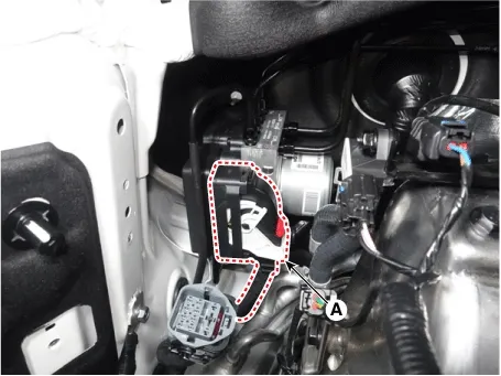
Pull up the lock of the ESC control unit (HECU) connector and then disconnect the connector (A).
|
| 3. |
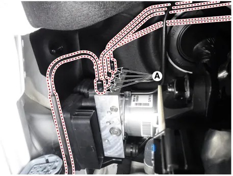
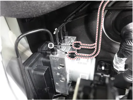
Separate the brake tube by removing the flare nuts connected to the ESC control unit (HECU).
|
| 4. |
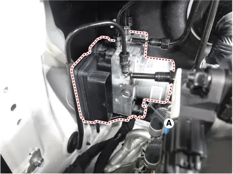
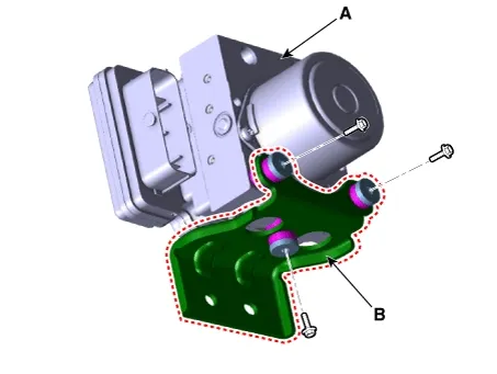
Remove the bracket mounting nuts and remove the ESC control unit (HECU) (A) from the vehicle.
|

| 5. |
Remove the bolts to remove the bracket (B) from the ESC control unit (HECU) (A).
|
| Installation |
| 1. |
Install in the reverse order of removal.
|
| 2. |
After installation, bleed the brake system.
(Refer to Brake system - "Brake Bleeding Procedures")
|
| 3. |
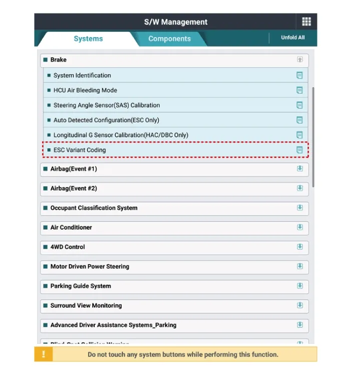
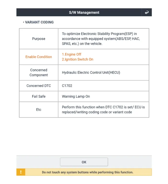
Conduct the Variant Coding.
|
| 4. |
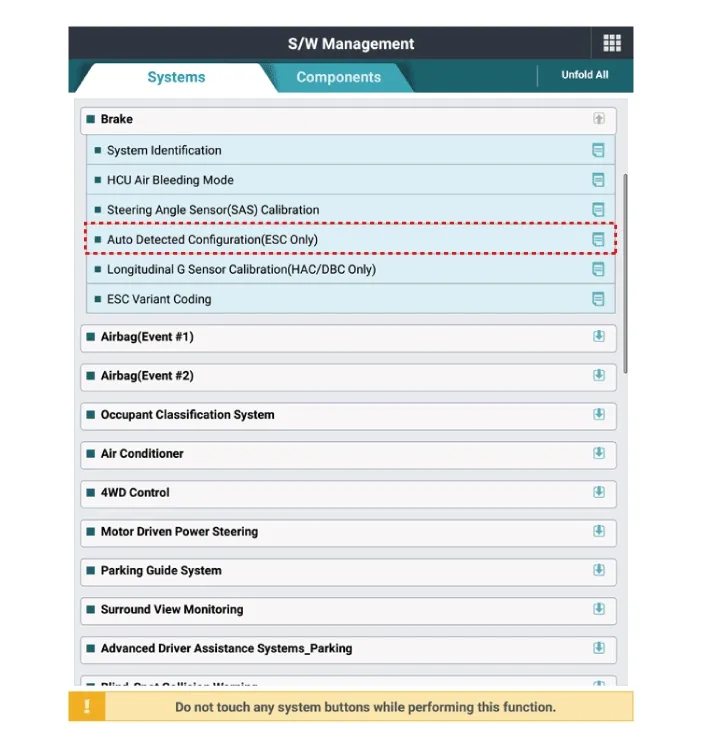
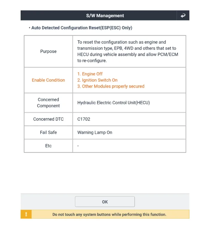
Conduct the Auto Detected Sensor Calibration.
|
| 5. |
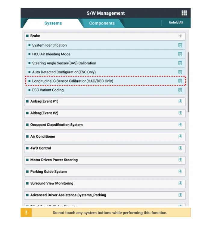
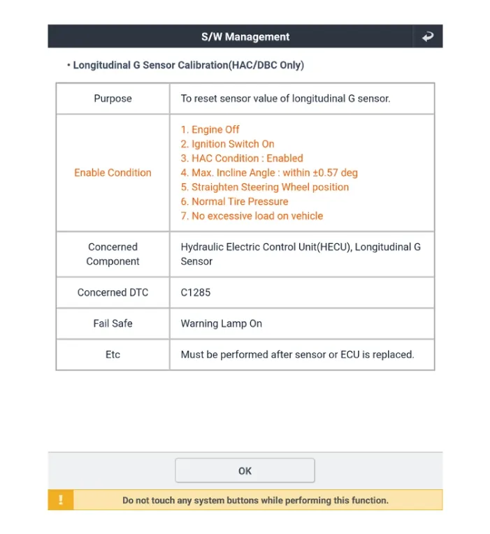
Conduct the Longitudinal G Sensor Calibration.
|
| 6. |
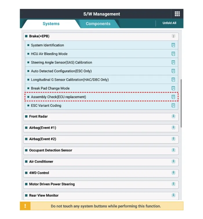
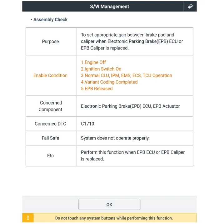
After replacing the ESC control unit execute the "Assembly Check (ECU replacement)" of the
additional function to check that the mounting is successful.
|
| Diagnostic procedure by using diagnostic scan tool |
Perform diagnostic procedure by using diagnostic device as shown below:
Connect self-diagnosis connector (16pins) located under the driver side crash pad to self-diagnosis device, and
then turn the self-diagnosis device after key is ON.
Select the "vehicle model" and "Brake" on KDS vehicle selection screen, then select OK.
[Variant Coding]
[Auto Detected Configuration]
[Longitudinal G Sensor Calibration]
[Assembly Check]
Components
1. Front Right (FR)2. Rear Left (RL)3. Rear
Right (RR)4. Front Left (FL)
5. Master Cylinder 16. Master Cylinder 27. ESC
Control u...
 ESC Control Unit Components and Components Location
ESC OFF Switch Description and Operation
Description
1.
The ESC OFF switch is for the user to turn off the ESC system.
...
 ESC OFF Switch Description and Operation. ESC OFF Switch Schematic Diagrams
See also:
Interior A
* These dimensions indicated in this figure are actual-measurement
dimensions. [ Unit : mm (inch) ]
...
Exhaust Manifold Repair procedures
Removal and installation
...
Front Wiper Motor Installation
1.
Install the wiper motor.
2.
Install the crank arm.
Torque :
12.7-17.6Nm (1.3-1.8, kgf.m, 9.4-13.0 lbf. ...
Manuals list
- Kia Sorento MQ4 2021-2026 Owners Manual
- Kia Sorento XM 2011-2015 Owners Manual
- Kia Sorento XM 2011-2015 Service Manual

Copyright © www.ksmanual.com 2014-2026 - 0.0651