
 Kia Sorento: Brake Pedal Repair procedures
Kia Sorento (MQ4, 2021-2026) Service Manual / Brake System / Brake System / Brake Pedal Repair procedures
| Removal |
| 1. |
Disconnect the (-) battery terminal.
|
| 2. |
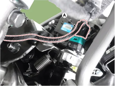
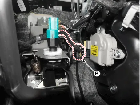
Disconnect the stop lamp switch connector (A) and pedal stroke sensor connector (B).
|

| 3. |
Remove the Crash Pad Lower Panel.
(Refer to Body - "Crash Pad Lower Panel")
|
| 4. |
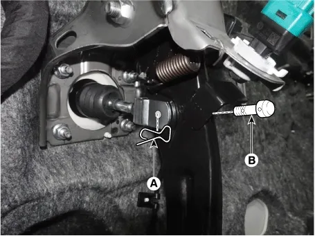
Separate the split pin (A) and clevis pin (B).
|
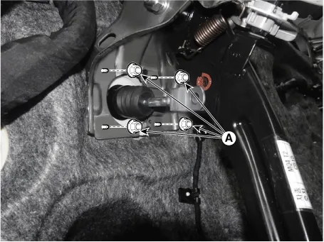
| 5. |
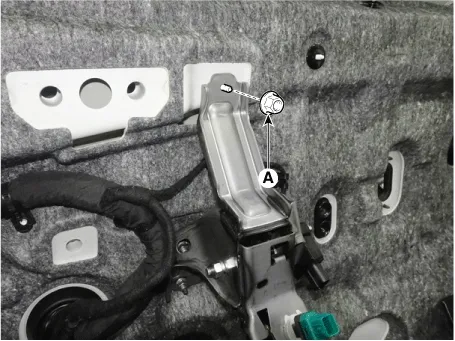
Remove the nuts (A) and then remove the brake pedal assembly.
|
| Inspection |
| 1. |
Check the brake pedal for bending or twisting.
|
| 2. |
Check the brake pedal return spring for damage.
|
| 3. |
Check the stop lamp switch.
(Refer to Brake System - "Stop Lamp Switch")
|
| Installation |
| 1. |
Install in the reverse order of removal.
|
Components
1. Brake member assembly2. Stop lamp switch3.
Brake pedal pad
4. Pedal stroke sensor5. Brake pedal arm...
 Brake Pedal Components and Components Location
Components
1. Brake member assembly2. Stop lamp switch3.
Brake pedal pad
4. Pedal stroke sensor5. Brake pedal arm...
 Stop Lamp Switch Components and Components Location
See also:
Smart Key
Smart Key Code Saving
1.
Connect the DLC cable of GDS to the data link connector (16 pins)
in driver side crash pad lower panel, turn the power on GDS.
...
Output Speed Sensor Specifications
▷ Type: Hall effect sensor
Operation condition ( ...
Manuals list
- Kia Sorento MQ4 2021-2026 Owners Manual
- Kia Sorento XM 2011-2015 Owners Manual
- Kia Sorento XM 2011-2015 Service Manual

Copyright © www.ksmanual.com 2014-2026 - 0.0592