
 Kia Sorento: Brake Booster Repair procedures
| Brake Booster Operation Test |
| 1. |
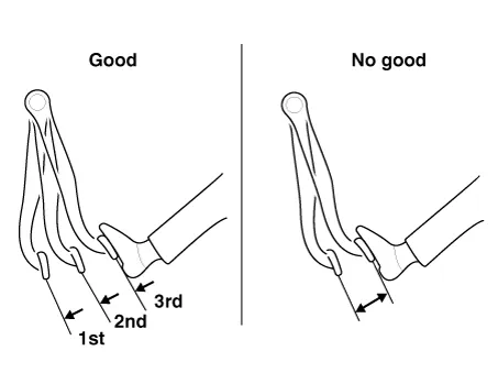
Run the engine for one to two minutes, and then stop it. If the pedal depresses fully initially but
gradually becomes higher in the successive attempts, the booster is operating properly. If the pedal height
remains unchanged, the booster is inoperative.
|
| 2. |
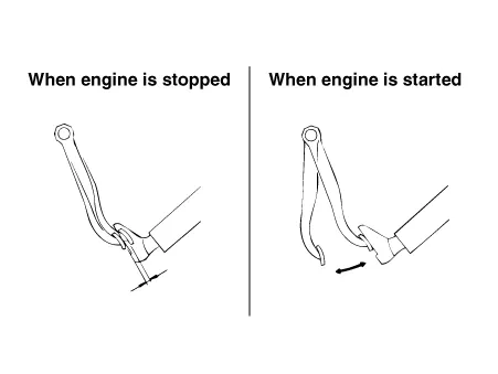
With the engine stopped, step on the brake pedal several times.
Then step on the brake pedal and start the engine. If the pedal moves downward slightly, the booster is in
good condition. If there is no change, the booster is inoperative.
|
| 3. |
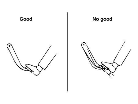
With the engine running, step on the brake pedal and then stop the engine. Hold the pedal depressed for 30
seconds. If the pedal height does not change, the booster is in good condition, and if the pedal rises, the
booster is inoperative.
If the three tests above are met,, the booster performance can be considered as in good condition.
Even if one of the three test above are unsatisfactory, check the check valve, vacuum hose and booster for
malfunction.
|
| Removal |
| 1. |
Remove the battery.
G 2.5 GDI THETA III - (Refer to Engine Electrical System -
"Battery")
G 2.5 T-GDI THETA III - (Refer to Engine Electrical System -
"Battery")
|
| 2. |
Remove the ECM bracket assembly.
G 2.5 GDI THETA III - (Refer to Engine Control / Fuel System - "Engine
Control Module (ECM)")
G 2.5 T-GDI THETA III - (Refer to Engine Control / Fuel System -
"Engine Control Module (ECM)")
|
| 3. |
Remove the Master Cylinder.
(Refer to Brake System - "Master Cylinder")
|
| 4. |
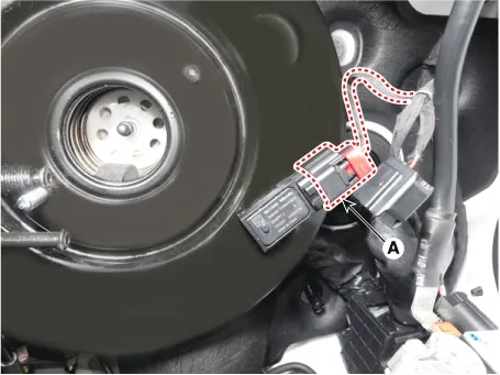
Disconnect the brake booster vacuum pressure sensor connector (A).
|
| 5. |
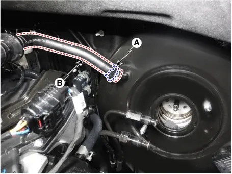
Remove the fixing clip (A) and separate the vacuum hose (B) from the brake booster.
|
| 6. |
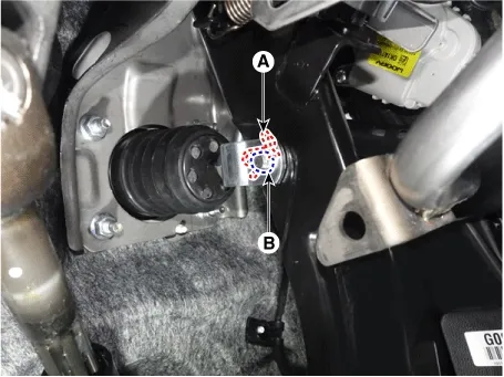
Remove the brake pedal split pin (A) and the clevis pin (B).
|
| 7. |
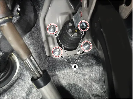
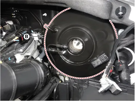
Remove the fixed nuts (A) and then remove the brake booster (B).
|
| Inspection |
| 1. |
Inspect the vacuum hose.
|

| 2. |
Check the boot for damage.
|
| Installation |
| 1. |
Install in the reverse order of removal.
|
| 2. |
After installation, bleed the brake system.
(Refer to Brake System - "Brake Bleeding Procedures")
|
| 3. |
Check the brake oil leakage and pedal operating condition.
|
 Brake Booster Components and Components Location
 Master Cylinder Components and Components Location
See also:
Fuel Tank Pressure Sensor (FTPS) Specifications. Fuel Tank Pressure Sensor (FTPS) Components and Components Location. Fuel Tank Pressure Sensor (FTPS) Description and Operation
Fuel Tank Pressure Sensor (FTPS) Specifications. Fuel Tank Pressure Sensor (FTPS) Components and Components Location
Fuel Tank Pressure Sensor (FTPS) Specifications
Specification
...
Cylinder Head Reassembly
Thoroughly clean all parts to be assembled.
Before installing the parts, apply fresh engine oil to all sliding and
...
46 Clutch Control Solenoid Valve (46/C_VFS) Installation
Installation
...
Manuals list
- Kia Sorento MQ4 2021-2026 Owners Manual
- Kia Sorento XM 2011-2015 Owners Manual
- Kia Sorento XM 2011-2015 Service Manual
