 Kia Sorento: Brake Bleeding Procedures
| Brake System Bleeding Procedures |
|
This work is to be performed by two people.
|
–
|
Main worker : Bleeds the system by manually opening and closing the bleed screw and detecting air
coming out of brake lines.
|
|
–
|
Assistant : Brake pedal operation and scanner operation inside the vehicle.
|
|
–
|
Working order :  Front RH →  Rear LH →  Front LH →  Rear RH
|
|
|
•
|
Do not reuse the drained brake fluid.
|
|
•
|
Always use genuine DOT4 brake Fluid, Using a non-genuine DOT4 brake fluid can cause corrosion and
decrease the life of the system.
|
|
•
|
Make sure that no dirt or other foreign matter is allowed to contaminate the brake fluid.
|
|
•
|
Be careful not to get brake fluid on the body or vehicle and, if so, wipe immediately with a clean
cloth.
|
|
•
|
Before air bleeding, check all the brake lines for leakage.
|
|
•
|
Check the installation of ABS and ESC control unit.
|
|
Air Bleeding Procedure (Step 1)
| 1. |
Remove the front and rear wheels and tires.
(Refer to Suspension System - "Wheel")
|
| 2. |
Fill the brake fluid to the "MAX" line.
|
Install a tool that can continuously supply brake fluid to the master cylinder reservoir, or supply
brake fluid so that the reservoir is always full during operation.
|

Air Bleeding Sequence and 1st, 2nd, and 3rd Bleeding Procedures (Play ▶) 
Notes When Refering Video
This video provides guidance for understanding complex or hard-to-follow procedures by showing each step
clearly.
As needed, the video also provides clear guidance on essential procedural steps, including adjustment and
diagnostic processes, the use of SSTs, and precautions to avoid component damage.
|
•
|
This video is created using common specifications and may differ from the actual vehicle.
|
|
•
|
The location and repair procedures of the parts may vary depending on vehicle model, model year,
region, and specifications.
|
|
•
|
Check the KDS guide for detailed information on how to use the KDS.
|
|
•
|
Check the manual for detailed maintenance procedures.
|
|
•
|
Unauthorized reproduction, distribution, or sharing of this video is prohibited.
|
|
| 3. |
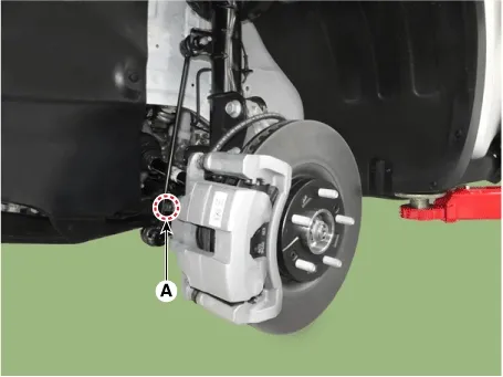
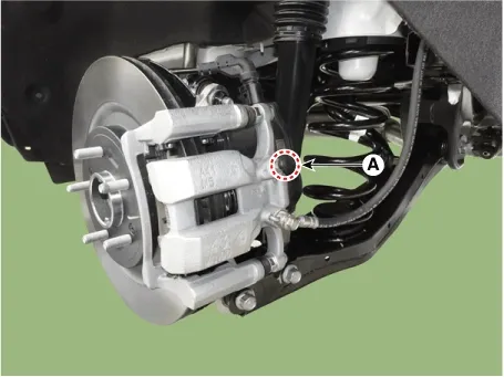
The main worker connects the clear hose to the wheel bleeder screw (A) and sends a signal to assistant to
depress the brake pedal.
|
| 4. |
The assistant to pump the brake pedal 2 times with normal brake force and then keep the brake pedal
depressed.
|
| 5. |
While the assistant is depressing the brake pedal, remove the bleeder screw (A) momentarily to remove the
air, and then fasten it again.
Tightening torque :
13.7 - 19.6 N·m (1.4 - 2.0 kgf·m, 10.0 - 14.4 lb·ft)
|
Front
Rear
|
•
|
Air may enter, so open and close the bleed screw only 1/4 of the way.
|
|
•
|
With the brake pedal pressed, open and close the bleeder screw.
|
|
|
| 6. |
Repeat the above procedure until no air bubbles appear in the brake fluid.
|
| 7. |
The assistant presses the brake pedal strongly twice and sends a stand-by signal to the main worker with
the brake pedal pressed.
|
| 8. |
While the assistant is depressing the brake pedal, remove the bleeder screw (A) momentarily to remove the
air, and then fasten it again.
Tightening torque :
13.7 - 19.6 N·m (1.4 - 2.0 kgf·m, 10.0 - 14.4 lb·ft)
|
Front
Rear
|
•
|
Air may enter, so open and close the bleed screw only 1/4 of the way.
|
|
•
|
With the brake pedal pressed, open and close the bleeder screw.
|
|
|
| 9. |
Repeat the above procedure until no air bubbles appear in the brake fluid.
|
| 10. |
When air bleeding is completed, fill the reservoir with brake fluid to the 'MAX' line.
|
If all of the conditions below are satisfied, the subsequent steps can be omitted.
|
•
|
If the ESC control unit is not replaced
|
|
•
|
If the reservoir tank is not replaced.
|
|
•
|
If the brake tube is not replaced.
|
|
•
|
If no bubbles appear in the brake fluid
|
|
|
| 11. |
Check the brake pedal stroke.
Pedal stroke
LHD : 129.0 mm (5.07 in)
RHD : 115.6 mm (4.55 in)
|
|
Air Bleeding Procedure (Step 2)
This procedure should be followed to ensure adequate bleeding of air and filling of the ESC unit, brake lines and
master cylinder with brake fluid.
| 1. |
Check the brake fluid level and replenish brake fluid until the 'MAX' (A) level.
|
Install a tool that can continuously supply brake fluid to the master cylinder reservoir, or supply
brake fluid so that the reservoir is always full during operation.
|
|
| 2. |
Perform the order below with the KDS.
(S/W Management → ABSESC - Brake → HCU Air Bleeding Mode)
|
•
|
Refer to the KDS screen for operating conditions and details..
|
|
•
|
The assistant operates the EPB switch simultaneously with the brake pedal to repeat
activation and deactivation.
|
|
•
|
When the EPB is repeatedly activated and deactivated, the worker hits the caliper body with
a rubber mallet.
|
|
|
| 3. |
When air bleeding is completed, fill the reservoir with brake fluid to the 'MAX' line.
|
| 4. |
Check the brake pedal stroke.
Pedal stroke
LHD : 129.0 mm (5.07 in)
RHD : 115.6 mm (4.55 in)
|
|
Air Bleeding Procedure (Step 3)
| 1. |
Perform the same operation as the "Air Bleeding Procedure (Step 1)".
|
| 2. |
Check the brake pedal stroke.
Pedal stroke
LHD : 129.0 mm (5.07 in)
RHD : 115.6 mm (4.55 in)
|
|
| 3. |
Install the front and rear wheel and tires.
(Refer to Suspension System - "Wheel")
|
Troubleshooting
Problem Symptoms Table
Use the table below to help you find the cause of the problem. The numbers indicate the priority of the likely
cau...



 Troubleshooting
 Brake System
