 Kia Sorento: Steering Column and Shaft Removal
Second Generation XM (2011-2025) / Kia Sorento XM 2011-2025 Service Manual / Steering System / Electric Power Steering / Steering Column and Shaft Removal
| 1. |
Disconnect the battery negative cable from the battery and then
wait for at least 30 seconds.
|
| 2. |
Turn the steering wheel so that the front wheels can face straight
ahead.
|
| 3. |
Remove the airbag module.
(Refer to Restraint - "Driver Airbag (DAB) Module and Clock Spring")
|
| 4. |
Disconnect the connector & lock nut (A) and then remove the steering
wheel by using special service tools (09561-11001).
|

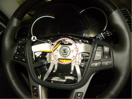
| 5. |
Remove the steering column shroud.
(Refer to Restraint - "Driver Airbag (DAB) Module and Clock Spring")
|
| 6. |
Remove the clock spring.
(Refer to Restraint - "Driver Airbag (DAB) Module and Clock Spring")
|
| 7. |
Remove the multifunction switch.
(Refer to Body Electrical System - "Multifunction switch")
|
| 8. |
Remove the crash pad lower panel.
(Refer to Body (Interior and Exterior) - "Crash Pad Lower Panel")
|
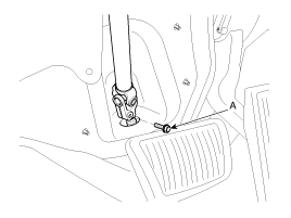
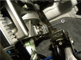
| 9. |
Loosen the bolt (A) and then disconnect the universal joint assembly
from the pinion of the steering gear box.
|
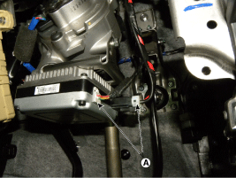
| 10. |
Disconnect all connectors (A) connected to the steering column.
|
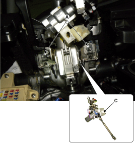
| 11. |
Remove the steering column (C) by loosening the mounting bolt
(B-1ea) and nut (A-2ea).
|
| 12. |
Install in the reverse order of removal.
|
| 13. |
Perform the steering angle sensor calibration.
(Refer to Electric Power Steering - " Repair procedures - ASP
Calibration")
|
 General Inspection
After or before servicing the EPS system, perform the troubleshooting
and test procedure as follows. Compare the system condition with normal condition
in the table below and if abnormal symp ...
 Steering Column and Shaft Disassembly
Universal joint assembly
1.
Loosen the bolt (A) and then disconnect the universal joint assembly
from the steering column assembly.
Tightenin ...
See also:
If the engine will not start
If engine doesn't turn over or turns over slowly
1.If your vehicle has an automatic transaxle, be sure the shift lever is in N
(Neutral) or P (Park) and the emergency brake is set.
2.Check the ...
Multimedia Jack Removal
Put on gloves to protect your hands.
...
External Amplifier Removal
External Amplifier
1.
Remove the passenger seat assembly.
(Refer to Body - "Front Seat Assembly")
2.
Remove the external a ...
Categories
- Home
- First Generation
- Second Generation
- Kia Sorento XM 2011-2025 Owners Manual
- Kia Sorento XM 2011-2025 Service Manual

Copyright ® www.ksmanual.com 2014-2025