 Kia Sorento: Balance Shaft & Oil Pump Removal
BSM (Balance Shaft Module) Chain System
| 1. |
Remove the timing chain.
(Refer to Timing System in this group)
|
| 2. |
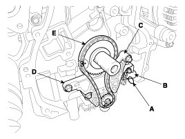
Install a stopper pin (A) after compressing the balance shaft chain
tensioner.
|
| 3. |
Remove the balance shaft chain tensioner (B).
|
| 4. |
Remove the balance shaft chain tensioner arm (C).
|
| 5. |
Remove the balance shaft chain guide (D).
|
| 6. |
Remove the balance shaft chain (E).
|
| 7. |
Remove the BSM (Balance Shaft Module) after removing the BSM mounting
bolts.
|
BSM (Balance Shaft Module)
| 1. |
Remove the under cover.
|
| 2. |
Remove the RH front wheel.
|
| 3. |
Drain the engine oil.
|
| 4. |
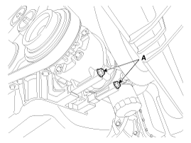
Remove the A/C compressor lower mounting bolts (A).
|
| 5. |
Remove the A/C compressor bracket (A).
|
| 6. |
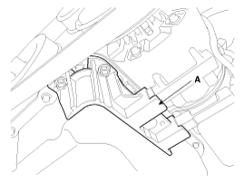
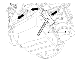
Remove the oil pan (A) after removing the bolts.
Insert the blade of SST (09215-3C000) between the ladder frame and oil
pan. Cut off applied sealer and remove the lower oil pan.
|
| 7. |
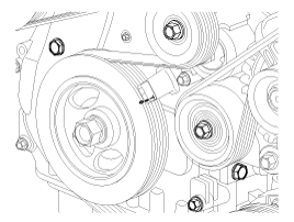
Set No.1 cylinder to TDC/compression.
|
| 8. |
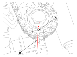
Put a mark on the timing chain (A) corresponding to the timing mark
(B) of the sprocket.
|
| 9. |
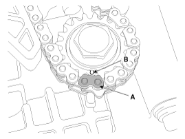
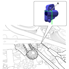
Insert a stopper pin (A) into the hole on the tensioner after compressing
the balance shaft chain tensioner piston.
|
| 10. |
Remove the BSM mounting bolts.
|
| 11. |
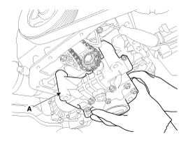
Remove the BSM (Balance Shaft Module) (A) while taking off the chain
from the sprocket.
|
 Balance Shaft & Oil Pump Components
1. Balance shaft & oil pump assembly
2. Balance shaft chain tensioner
3. Balance shaft chain
4. Balance shaft chain sprocket
5. Balance shaft chain guide
6. Balance shaft ...
 Balance Shaft & Oil Pump Installation
BSM(Balance Shaft Module) Chain System
1.
The key of crankshaft should be aligned with the mating face of main
bearing cap. As a result of this, the piston of No.1 cylinde ...
See also:
Opening the tailgate
The tailgate is locked or unlocked when all doors are locked or unlocked
with the key, transmitter (or smart key) or central door lock switch.
If unlocked, the tailgate can be opened by press ...
Keep your vehicle clean
The best way to prevent corrosion is to keep your vehicle clean and free of corrosive
materials. Attention to the underside of the vehicle is particularly important.
If you live in a high-corrosi ...
Ignition Coil Description
An ignition coil is an induction coil in an engine's ignition system which
transforms the battery's low voltage to the high voltage needed to create an
electric spark in the spark plu ...


 arrow.
 arrow around more
than 2/3 edge of the oil pan, remove it from the ladder
frame.