 Kia Sorento: Schematic Diagrams
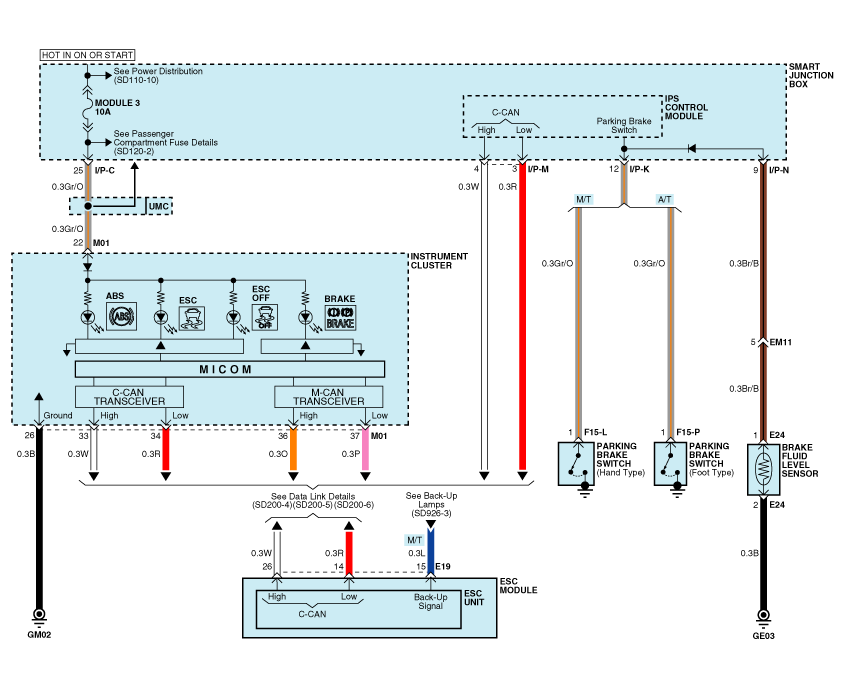
Circuit Diagram - ESC (1)
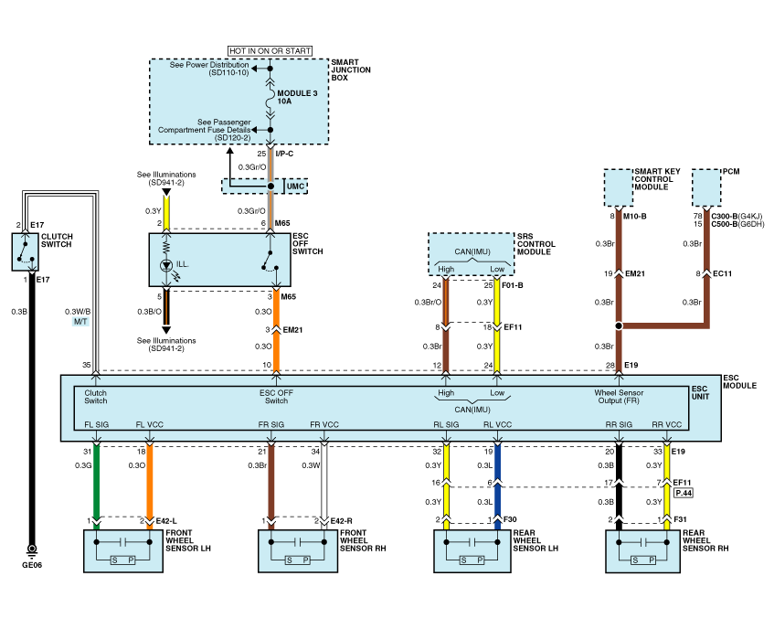
Circuit Diagram - ESC (2)
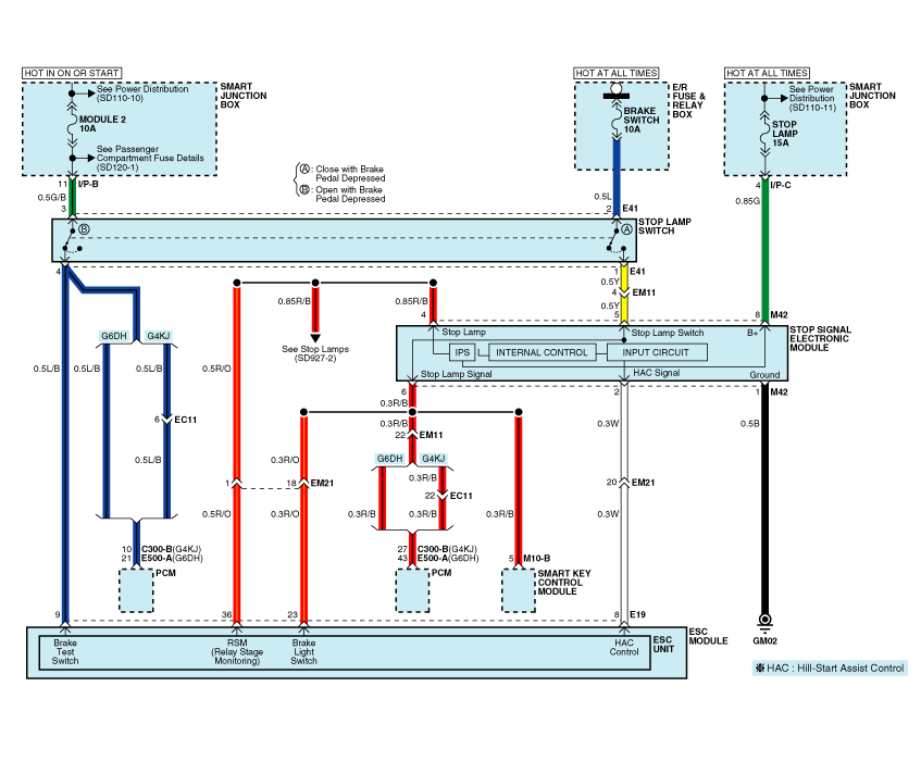
Circuit Diagram - ESC (3)
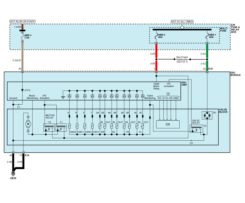
Circuit Diagram - ESC (4)
ESC connector input/output
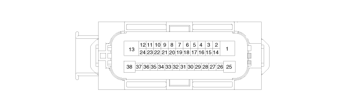
| Connector Terminal |
Specification |
|
| Pin No |
Description |
|
| 29 |
IGNITION1(+) |
High level of wake up voltage : 4.5V < V < 16.0V Low level of wake up voltage : V < 2.4V Max. current : I < 50mA |
| 25 |
POS. BATTERY 1.(SOLENOID) |
Over voltage range : 17.0 ┬▒ 0.5V Operating voltage range : 10.0 ┬▒ 0.5V < V < 16.0 ┬▒ 0.5V Low voltage range : 7.0 ┬▒ 0.5V < V < 9.5 ┬▒ 0.5V Max. current : I < 40A Max. leakage current : I < 0.25mA |
| 1 |
POS. BATTERY 2.(MOTOR) |
Operating voltage range: 10.0 ┬▒ 0.5V < V < 16.0 ┬▒ 0.5V Rush current : I < 110A Max current : I < 40A Max leakage current : I < 0.25mA |
| 38 |
GROUND |
Rated current : I <550mA Max. current: I < 40A |
| 13 |
PUMP MOTOR GROUND |
Rush current : I < 110A Max current : I < 40A |
| 23 |
BRAKE LIGHT SWITCH |
Input voltage (Low) : V < 2V Input voltage (High) : V > 6V Max. Input current : I < 3mA (@12.8V) |
| 10 |
ESC ON/OFF SWITCH |
|
| 28 |
SENSOR FRONT RIGHT OUTPUT |
External pull up resistance : 1 KΩ < R Output duty :50 ┬▒ 20% |
| 14 |
CAN BUS LINE(LOW) |
Max. Input current : I < 10mA |
| 26 |
CAN BUS LINE(HIGH) |
|
| 18 |
SENSOR FRONT LEFT POWER |
Output voltage : V_BAT1 -0.6V ~ V_BAT1 -1.1V Output current : Max 30mA |
| 34 |
SENSOR FRONT RIGHT POWER |
|
| 19 |
SENSOR REAR LEFT POWER |
|
| 33 |
SENSOR REAR RIGHT POWER |
|
| 31 |
SENSOR FRONT LEFT SIGNAL |
Input current LOW : 5.9 ~ 8.4mA Input current HIGH : 11.8 ~ 16.8mA Frequency range : 1 ~ 2500Hz Input duty : 50 ┬▒ 10% |
| 21 |
SENSOR FRONT RIGHT SIGNAL |
|
| 32 |
SENSOR REAR LEFT SIGNAL |
|
| 20 |
SENSOR REAR RIGHT SIGNAL |
|
| 12 |
CAN SENSOR LINE (HIGH) |
Max. input current : I < 10mA |
| 24 |
CAN SENSOR LINE (LOW) |
|
| 8 |
HAC RELAY DRIVE |
Max. Current : I< 180mA Max.Output Low Voltage : V< 1.2V |
| 9 |
BRAKE SWITCH |
Input voltage (Low) : V < 2V Input voltage (High) : V > 6V Max. Input current : I < 10mA |
| 36 |
RELAY STATE MONITORING |
|
| 35 |
CLUTCH SWITCH |
Input voltage (Low) : V < 2V Input voltage (High) : V > 6V Max. Input current : I < 50mA (@12.8V) |
 ESC Operation Mode
ESC Hydraulic System Diagram
1.
ESC Non-operation : Normal braking.
Solenoid valve
Continuity
Valve
Motor ...
 Failure Diagnosis
1.
In principle, ESC and TCS controls are prohibited in case of ABS
failure.
2.
When ESC or TCS fails, only the failed system control is pr ...
See also:
ESC Operation Mode
ESC Hydraulic System Diagram
1.
ESC Non-operation : Normal braking.
Solenoid valve
Continuity
Valve
Motor ...
Battery Removal
1.
Disconnect the battery (-) terminal and (+) terminal (A).
2.
Remove the battery mounting bracket (B) and the insulation pad
and then rem ...
Oil Pan Installation
1.
Install the oil pan.
(1)
Using a gasket scraper, remove all the old sealant material
from the gasket surfaces.
...
Categories
- Home
- First Generation
- Second Generation
- Kia Sorento XM 2011-2025 Owners Manual
- Kia Sorento XM 2011-2025 Service Manual
