 Kia Sorento: Front Driveshaft Removal and Installation
Second Generation XM (2011-2025) / Kia Sorento XM 2011-2025 Service Manual / Driveshaft and axle / Driveshaft Assembly / Front Driveshaft Removal and Installation
| 1. |
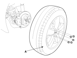
Remove the front wheel and tire (A) from front hub .
|
| 2. |
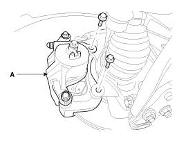
Remove the brake caliper mounting bolts, and then place the brake
caliper assembly (B) with wire.
|
| 3. |
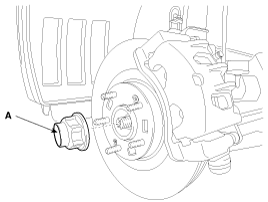
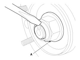
Remove the coking nut (A).
|
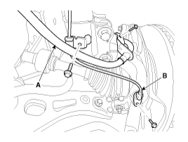
| 4. |
Remove the brake hose (A) and wheel speed sensor (B).
|
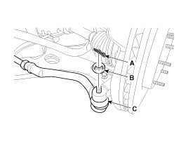
| 5. |
Remove the tie rod end ball joint (C) from the knuckle.
|
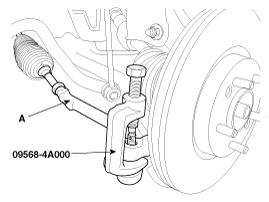
| 6. |
Disconnect the ball joint(A) from knuckle using the special tool
(09568-4A000).
|
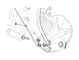
| 7. |
Remove the lower arm (A) mounting bolt and nut from the knuckle.
|
| 8. |
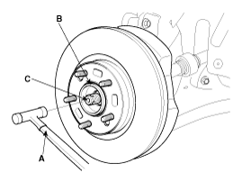
Using a plastic hammer (A), disconnect driveshaft (C) from the
axle hub (B).
|
| 9. |
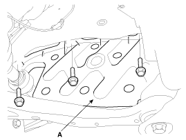
Remove the RH side cover (A).
|
| 10. |
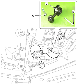
Remove the mounting bolts (A,B) of Upper roll rod bracket (C).
|
| 11. |
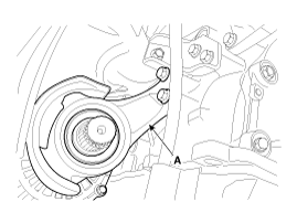
Loosen the inner shaft mounting bolts and then disconnect the
inner shaft (A).
|
| 12. |
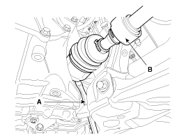
Insert a pry bar (A) between the transaxle case and joint case,
and separate the drive shaft (B) from the transaxle case.
|
| 13. |
Install in the reverse order of removal.
|
 Front Driveshaft Components
1. Front driveshaft (LH)
2. Inner shaft bearing bracket
3. Front driveshaft (RH)
[LH]
1. BJ assembly
2. Clip
3. BJ boot band
4. BJ bo ...
 TJ Joint Components
[LH]
1. BJ assembly
2. BJ circlip
3. BJ boot band
4. BJ boot
5. Shaft
6. TJ boot band
7. TJ boot
8. Spider assembly
9. Retainer ring
10. ...
See also:
Specifications
Memory Power Seat Unit
Item
Specification
Rating voltage
DC 12V
Operation voltage
DC 9V ~ 16V
Operation temperaure
-30┬░C ...
Components Location
1. Fuel tank
2. Fuel pump
3. Fuel filter
4. Fuel pressure regulator
5. Canister
6. Fuel tank air filter
7. Fuel tank band
8. Fuel tank pressure sensor (FTPS)
9. ...
Removal
1.
Disconnect the negative (-) battery terminal.
2.
Remove the steering column upper and lower shrouds (A) after removing
3 screws.
...
Copyright ® www.ksmanual.com 2014-2025


